
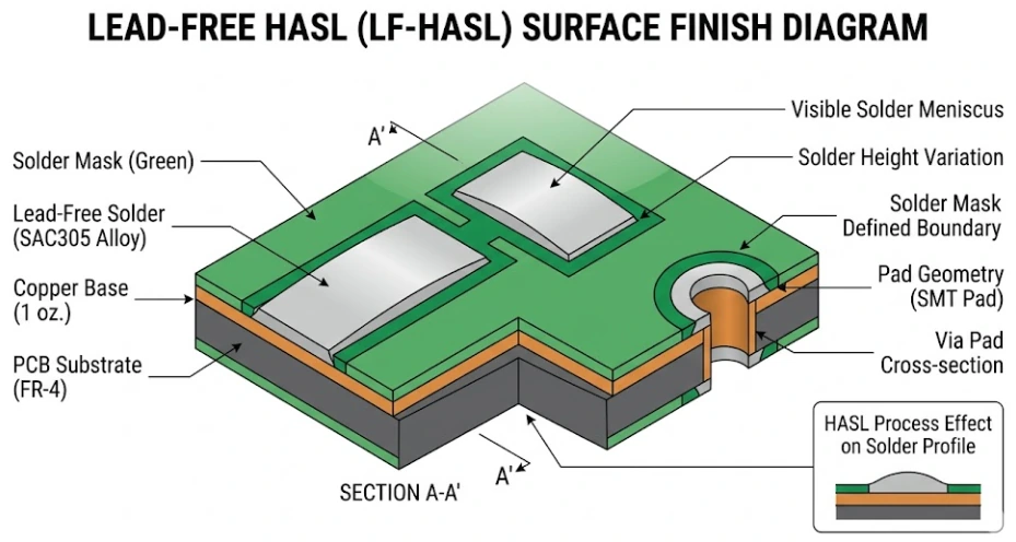
Lead-free solder melts at a higher temperature than leaded solder, and that one fact drives most of the differences between them. The common lead-free alloy for PCB assembly, SAC305 (tin, 3% silver, 0.5% copper), melts across a narrow range of about 217 to 220 °C. Classic eutectic leaded solder, Sn63Pb37, melts at a single point, 183 °C. Lead-free reflow therefore runs roughly 20 to 30 °C hotter, which narrows the gap between "hot enough to solder" and "too hot for the parts and the board."
Leaded solder is still easier to work with and very reliable, but RoHS restricts lead in most electrical and electronic equipment sold in the EU and in markets with similar rules. Leaded solder is now limited to products outside RoHS scope or covered by a specific exemption. This guide compares the alloys, answers "what temperature does solder melt?", explains when leaded solder is still allowed, and lists what to specify in an assembly RFQ.
Key takeaways
- SAC305 melts at about 217 to 220 °C; Sn63Pb37 melts at 183 °C; Sn60Pb40 melts over a small range from 183 to about 190 °C.
- Lead-free reflow peaks typically run in the 235 to 250 °C range, compared with roughly 205 to 225 °C for tin-lead paste. Always follow the paste maker's profile.
- Use lead-free solder by default for products sold under RoHS rules. Use leaded solder only when the product is out of scope or an applicable exemption covers it, and record that decision.
- Components, laminate, and surface finish must be rated for the lead-free process temperature. That includes moisture sensitivity levels at the higher peak.
- Mixing alloys, such as a lead-free BGA on a tin-lead line, needs a deliberate profile and an engineering decision, not a default.
What temperature does solder melt?
The melting point of solder depends on the alloy. Eutectic alloys melt at one temperature. Non-eutectic alloys pass through a "pasty" range between solidus (where melting starts) and liquidus (where the alloy is fully liquid).
| Alloy | Composition | Melting point or range | Typical reflow peak | Wetting | Relative cost | RoHS status |
|---|---|---|---|---|---|---|
| Sn63Pb37 | 63% tin, 37% lead | 183 °C (eutectic) | About 205 to 225 °C | Excellent | Low | Contains lead; only for out-of-scope or exempt uses |
| Sn60Pb40 | 60% tin, 40% lead | About 183 to 190 °C | Similar to Sn63Pb37 | Excellent | Low | Contains lead; same restriction |
| SAC305 | Sn96.5 / Ag3.0 / Cu0.5 | About 217 to 220 °C | About 235 to 250 °C | Good; slower spread than SnPb | Higher (silver content) | Lead-free |
| SAC0307 | Sn99.0 / Ag0.3 / Cu0.7 | About 217 to 228 °C | Similar to or slightly above SAC305 | Fair to good | Lower than SAC305 | Lead-free |
| Sn99.3Cu0.7 | Tin with 0.7% copper | 227 °C (eutectic) | Higher than SAC305 | Fair | Low | Lead-free; common in wave and hand soldering |
| SN100C | Sn-Cu with nickel and germanium | About 227 °C | Similar to Sn-Cu | Good for a Sn-Cu alloy | Low to medium | Lead-free; common in wave and selective soldering |
| Sn42Bi58 | 42% tin, 58% bismuth | 138 °C (eutectic) | About 160 to 180 °C | Fair | Medium | Lead-free; low-temperature uses |
These are typical published values. Exact solidus, liquidus, and recommended profiles come from the paste or bar solder datasheet for the product you buy.
How hot is a soldering iron for lead-free and leaded solder?
The iron tip runs well above the alloy's melting point so heat can transfer into the joint quickly. Many technicians set roughly 315 to 345 °C for tin-lead and 340 to 370 °C for lead-free work, then adjust for tip size and thermal mass. Too much heat damages pads and parts; too little causes cold joints. The hand soldering guide covers tip and temperature selection.
Lead vs lead-free solder: what changes in the process
Switching from leaded to lead-free solder changes the process, the materials, and how joints look:
- Higher process temperature. Peak reflow rises by about 20 to 30 °C. Parts, connectors, and plastics need ratings that cover it, and the board laminate must handle repeated lead-free cycles without delamination. The high-Tg PCB page explains when a higher-Tg laminate is worth specifying.
- Narrower process window. The gap between the solder's melting point and the parts' maximum rating shrinks, so the oven profile needs closer control, especially on boards with large thermal mass differences.
- Slower wetting. Lead-free alloys spread less readily, so flux activity, pad finish, and stencil design matter more.
- Different appearance. Lead-free joints look duller and grainier than tin-lead joints. That is normal and is not, by itself, a sign of a cold joint.
- Higher material cost. Silver-bearing alloys like SAC305 cost more than tin-lead. Low-silver alloys reduce cost but can change wetting and reliability.
- More dross and tip wear. High-tin alloys attack iron tips and wave solder pots faster.
Types of solder alloys used in PCB assembly
Different steps on the same assembly line may use different alloys:
- SMT reflow paste. SAC305 is the most common lead-free choice. Sn63Pb37 is the common leaded choice. Low-silver SAC and bismuth-containing alloys are used for cost or temperature reasons.
- Wave and selective soldering. Tin-copper alloys such as Sn99.3Cu0.7 and SN100C, or SAC alloys, are common because they cost less and behave well in a solder pot.
- Hand soldering and rework. Flux-cored wire in SAC305, Sn-Cu, or Sn63Pb37, matched to the alloy already on the board.
- Low-temperature soldering. SnBi and SnBiAg alloys for heat-sensitive parts or step soldering, with care because bismuth joints are more brittle under shock and can behave badly if lead contamination is present.
The solder paste selection guide covers paste type, powder size, and flux class in more detail.
When is leaded solder still allowed?
Leaded solder is still legal and still used, but only where the rules allow it. Under the EU RoHS Directive, lead is restricted to 0.1% by weight in each homogeneous material, with a list of time-limited exemptions in the directive's annexes. Practical cases where leaded solder may still be used include:
- Products outside RoHS scope. Examples often cited are certain military, space, and large-scale fixed installations. Scope must be checked against the current directive, not assumed.
- Applications covered by an exemption. High-melting-temperature lead solders (alloys with 85% or more lead) are allowed only in specific uses listed in Annex III. In 2025 the EU replaced the old single 7(a) entry with narrower sub-entries 7(a)-I to 7(a)-VII, each with its own scope and expiry date, so check the current text before relying on one. These alloys are not a substitute for ordinary Sn63Pb37 assembly.
- Markets without equivalent restrictions, where the product will not be sold in a restricted market.
- Repair of legacy products built before the restriction, where the rules permit it.
Exemptions are narrow and change over time. The product owner, not the assembler, decides whether an exemption applies, and that decision should be documented. The RoHS compliant PCB guide explains how RoHS applies to boards and assemblies.
Lead-free soldering process window and component ratings
A lead-free process works only if every material on the board survives it. Check these before you release a lead-free build:
- Component peak temperature rating. Many SMD packages are classified under J-STD-020, which sets the peak body temperature the part must survive and its moisture sensitivity level. Lead-free classification uses higher peaks than tin-lead classification, and a part rated only for tin-lead may not survive.
- Moisture sensitivity. A higher peak increases the risk of package cracking from absorbed moisture. Store and bake moisture-sensitive devices per J-STD-033.
- Board laminate. Choose a laminate with suitable Tg and decomposition temperature for the number of reflow cycles, especially on thick or multilayer boards.
- Surface finish. ENIG, OSP, immersion silver, immersion tin, and lead-free HASL are all compatible with lead-free assembly; each has trade-offs in flatness and storage. See the PCB surface finishes guide.
- Profile. Set soak, time above liquidus, and peak from the paste datasheet, then measure on the populated board. The reflow profile basics explain each zone.
Mixed assemblies: a lead-free BGA on a leaded line
Mixing alloys happens more than you might expect, usually because a part is only sold with lead-free balls or terminations.
- Backward compatibility (lead-free parts, tin-lead paste). A SAC ball does not fully melt at a typical tin-lead peak. If the profile is too low, the ball and paste do not mix properly and the joint can be weak or show head-in-pillow defects. The usual fix is a raised tin-lead profile that still respects other parts' ratings, or reballing the part with tin-lead balls.
- Forward compatibility (tin-lead parts, lead-free paste). Older parts may not be rated for lead-free peaks, and small amounts of lead in bismuth-containing joints can form low-melting phases.
- Documentation. Mixed builds should be called out on the assembly drawing and in the BOM so the assembler sets the right profile.
Mixed assembly also affects compliance: a single leaded joint makes the assembly non-compliant if RoHS applies.
Reliability: wetting, voids, and tin whiskers
Both alloy families can produce reliable joints when the process is right. The differences show up at the edges:
- Thermal cycling. SAC joints often perform well in thermal cycling, but results depend on the package, board thickness, and test profile. Low-silver alloys can behave differently.
- Drop and shock. High-silver SAC joints can be more brittle in drop tests than tin-lead joints. Low-silver alloys and doped alloys are sometimes chosen for handheld products for this reason.
- Voiding. Lead-free pastes can show more voiding under large thermal pads and BGAs. Paste choice, stencil design, and profile control it.
- Tin whiskers. Pure tin and high-tin finishes can grow whiskers over time, which can short adjacent conductors. Lead was a natural whisker suppressant. High-reliability programs use matte tin with mitigation, nickel underlayers, conformal coating, or other controls defined in their reliability plans.
What to specify in the RFQ
Tell the assembler exactly which solder process you expect. Include:
- Process type: lead-free (state the alloy, for example SAC305) or tin-lead (state the alloy and the reason)
- Whether the product must comply with RoHS, and any exemption you are relying on
- Paste type and flux class if you require a specific product, or approval to use the assembler's standard
- Alloy for wave, selective, and hand soldering steps
- Any mixed-alloy parts, such as lead-free BGAs on a tin-lead build
- Laminate and surface finish suitable for the process temperature
- Moisture-sensitive device handling requirements
- Acceptance standard (IPC-A-610 class) and any X-ray voiding limits
- Compliance documents you need: material declarations, certificates of conformance
Why build lead-free or leaded assemblies with APTPCB?
APTPCB's lead-free SMT assembly runs on 10-zone nitrogen reflow lines with thermal profiling, and its dual-nozzle nitrogen selective soldering supports both SnPb and Pb-free alloys for through-hole parts. The engineering review checks component ratings, laminate, finish, and profile against the alloy you specify, and flags mixed-alloy parts before the build. If you need a leaded build, state the alloy and the compliance basis on the drawing so the process and records match.
Relevant standards and references may include:
- EU RoHS Directive 2011/65/EU and its amendments
- J-STD-006: requirements for electronic grade solder alloys
- J-STD-001: requirements for soldered electrical and electronic assemblies
- J-STD-020: moisture/reflow sensitivity classification for nonhermetic SMDs
- J-STD-033: handling of moisture/reflow sensitive SMDs
- IPC-A-610: acceptability of electronic assemblies
Frequently asked questions
What is the melting point of lead-free solder?
The most common lead-free alloy, SAC305, melts between about 217 and 220 °C. Tin-copper alloys such as Sn99.3Cu0.7 melt at about 227 °C, and low-temperature tin-bismuth alloys melt at about 138 °C. Check the datasheet for the exact alloy you use.
What is the melting point of 60/40 and 63/37 solder?
Sn63Pb37 is eutectic and melts at 183 °C. Sn60Pb40 is close to eutectic and melts over a small range, from 183 °C to about 190 °C. Both are leaded solders and are restricted under RoHS for most products.
Is lead-free solder as good as leaded solder?
For most products, yes, when the process is controlled. Lead-free solder needs higher temperatures and wets more slowly, so profiles, finishes, and component ratings matter more. Tin-lead solder is easier to process and remains in use where it is permitted, mainly in exempt or out-of-scope products.
Can you mix leaded and lead-free solder?
You can, but it should be a deliberate engineering decision. A lead-free BGA on a tin-lead line needs a profile hot enough to fully melt and mix the ball, and the assembly is no longer RoHS compliant if any leaded solder is used where RoHS applies.
Is leaded solder still legal?
Yes, in products outside the scope of RoHS and similar laws, in applications covered by a valid exemption, and in markets without equivalent restrictions. Exemptions are specific and time-limited, so the product owner should confirm and document the basis.
What type of solder is used for electronics?
Most new PCB assemblies use lead-free solder, typically SAC305 paste for SMT and tin-copper or SAC alloys for wave, selective, and hand soldering. Tin-lead Sn63Pb37 is still used where allowed, and tin-bismuth alloys are used for low-temperature processes.
Choose the alloy, then the process
The alloy decision comes first. It sets the reflow profile, the component and laminate ratings, the surface finish, and the compliance documents. Default to lead-free for products sold under RoHS rules, use leaded solder only with a documented reason, and write both the alloy and the compliance basis into the RFQ so the assembler can build exactly what you intend.