
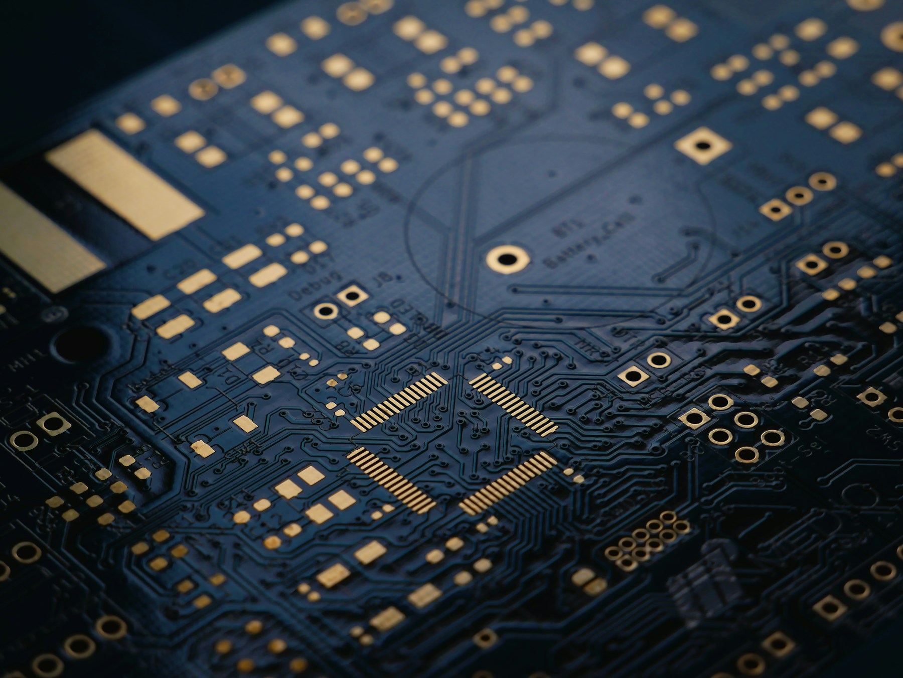
When needed, PCB drill desmear is intended to remove residue left by mechanical drilling before hole metallization, so the intended inner-layer copper can be reached by the subsequent process. The useful question is not simply whether a board went through a desmear cycle: it is whether the selected treatment and inspection evidence are appropriate for the actual materials, holes and acceptance requirements.
If a section shows material at an inner-layer connection, record what is visible and where it is before assigning a cause. Residue at an interface and a separation between copper surfaces call for different investigations. For coupon selection and the broader sampling plan, see microsection coupon strategy.
What happens between drilling and plating?
Mechanical drilling can leave resin-containing debris on a hole wall and across the exposed ends of inner-layer copper. Hole preparation addresses that residue before activation and copper deposition. The complete route depends on the laminate, bondply or prepreg, hole geometry, drilling conditions and the fabricator's qualified metallization process.
Drilling quality matters upstream. Isola's 370HR processing guide, in its Hole Wall Preparation section, discusses material-specific desmear and suggests examining samples after drilling and deburring and again after desmear. The first observation helps assess debris and drilling damage; the second helps assess treatment effectiveness and surface condition. These are material-specific recommendations, not evidence that every PCB needs the same treatment or that every order includes these inspections.
How is PCB desmear performed?
Depending on the material and qualified fabrication route, hole-wall preparation may use a chemical treatment or plasma treatment. These are different process routes, and neither is appropriate for every laminate or construction. A mixed stack can contain materials that respond differently, so the fabricator must review the whole construction, including the bonding materials.
The process is part of a larger sequence: drilling and deburring, any required hole-wall preparation, surface conditioning or activation, and copper deposition. The exact sequence and controls depend on the selected route. A clean-looking hole wall or a statement that a treatment was used does not establish that every interface meets the order's requirements.
What does the observed interface actually show?
The inner-layer copper end, the surrounding dielectric and the deposited hole-wall copper are distinct features. Record the hole, layer, interface and specimen condition before describing a defect. A section can be ambiguous: preparation artifacts, the view plane or the contrast between materials can make an interface difficult to interpret.
| Observation | What it suggests, and what it does not establish | Next question or evidence |
|---|---|---|
| Material appears between an inner-layer copper end and the deposited copper | Residue is a possibility, but appearance alone does not identify its composition or prove which operation caused it. | Preserve an image of the identified interface and sample condition. Compare with a representative post-drill or post-desmear sample if available; ask whether further material analysis is justified. |
| A gap appears at the inner-layer copper/deposited-copper interface | A visible separation is not, by itself, proof of residual smear or of a desmear failure. Copper surface condition, deposition and thermal history also need review. | Compare the as-polished view with any etched view, identify whether the specimen was thermally stressed, and review drilling, preparation and metallization records together. If the view is unclear, agree additional examination with the laboratory. |
| The plated wall has a local void away from an identified inner-layer interface | A plating discontinuity does not identify desmear as its sole cause. | Document hole size, layer and panel location; compare other representative samples and review cleaning, activation and plating evidence as well as desmear controls. |
| The dielectric is recessed or reinforcement is exposed | This describes geometry at the sampled location; it does not automatically establish an unacceptable etchback or the cause of later failure. | Identify the material and intended requirement, sample state and measurement method. Compare the local observation with the applicable drawing and specification before changing the process. |
Isola's interconnect-defect presentation distinguishes debris at the interconnect from separation and discusses causes across drilling, cleaning and copper deposition. It cautions that increasing desmear may not address the underlying cause and can worsen some separation problems. The presentation is technical guidance, not a diagnosis of a particular board.
For example, suppose a post-stress section shows a gap at one inner-layer connection. Before asking for a longer desmear cycle, identify the affected layer and hole, retain the as-polished image, and check whether an unstressed comparable sample exists. If material is suspected at the interface, ask how it was identified; if the gap is clear but its origin is not, review surface preparation, copper deposition and the stress history as well. This is an investigation path, not a finding about a production lot.
How much does a microsection prove?
A microsection gives a local view of the prepared specimen in the section plane. Its value depends on whether the sampled hole and panel position represent the feature being evaluated, and on preparation, magnification and image quality. A clear image of one interface does not establish the condition around the entire circumference or across every hole in the lot.
Ask the laboratory to identify the coupon or board, panel position, hole and layer, sample condition, section plane, scale and applicable acceptance reference. Distinguish an as-polished image from one taken after etching: both can be useful, but observations may not correspond one-to-one and should not be treated as interchangeable evidence. Document the existing view before further preparation when applicable. If the interface is obscured, agree on further preparation or analysis before deciding what the image shows.
Electrical continuity is a separate observation: it records connectivity under the conditions of that test. It does not alone establish interfacial bond strength or service life. Likewise, a microsection is not a substitute for any electrical or thermal testing required by the order. Define the applicable test, specimen condition and acceptance criteria with the fabricator and quality team.
Is desmear the same as etchback?
Desmear addresses residue from hole formation. Etchback deliberately removes dielectric around the inner-layer copper to produce a specified geometry. A process may affect both, but the intended result and acceptance should be stated separately. More removal is not automatically better.
The material can change the decision. Isola's 370HR guide distinguishes desmear and etchback for that material system. Rogers' RO4003C, RO4350B, RO4835 and Anteo quick reference says chemical or plasma desmear may be needed for the named products and does not recommend etchback. Neither instruction is a universal rule for other materials or mixed stackups. Confirm the current guidance for every material in the proposed construction and the fabricator's qualified process.
What should be agreed before fabrication?
Provide the approved stackup, including laminate and bondply/prepreg grades, the fabrication drawing, drill files, hole sizes and board thickness. Identify critical inner-layer connections and the applicable customer specification and revision. Tell the fabricator about planned thermal exposures and any restrictions on material substitution.
Then agree which hole structures and panel positions the inspection samples represent, whether samples are examined before or after thermal stress, and which images or records are required. Define the acceptance reference and what happens when an interface is unclear or fails the agreed requirement. Request confirmation of feasibility, scope, cost and lead-time effects; do not assume a particular report or process is included.
The fabricator selects and controls its production process. The customer and supplier agree the order's acceptance evidence; product and system qualification require their own plan.
For a project discussion, send the stackup and inspection requirements through the quote page or contact APTPCB.
Frequently Asked Questions
What is PCB desmear?
Desmear is hole-wall preparation intended to remove residue left by hole formation before subsequent metallization. The treatment and its need depend on the construction and fabricator's process.
Is desmear always required after drilling?
Not in every construction. The fabricator should assess the actual laminate, bonding materials, hole structure and metallization route against applicable product guidance and order requirements.
Is desmear the same as etchback?
No. Desmear addresses residue; etchback deliberately removes dielectric to produce a specified geometry. A treatment may affect both, so define the intended result and acceptance separately.
Does more desmear always improve a connection?
No. An observed separation can have several possible causes. Increasing treatment without identifying the condition may fail to address the cause and can create other problems.
Can one microsection prove that every hole is acceptable?
No. A section shows a local plane in the sampled specimen. Its coverage depends on the sampling plan and preparation, and it cannot by itself establish the condition of every hole or interface.
Does a continuity test prove the long-term reliability of a plated hole?
No. It establishes connectivity under the test conditions. Other evidence may be needed under the agreed inspection and product qualification plans.
References
- Isola, 370HR Laminate and Prepreg Processing Guide, Part 5, Hole Wall Preparation; accessed 2026-11-12. Confirm the current document and the material construction with the supplier.
- Isola, ICDs (InterConnect Defects), technical presentation; accessed 2026-11-12. Its examples and process guidance are not universal acceptance criteria.
- Rogers Corporation, RO4003C / RO4350B / RO4835 / Anteo Laminates Quick Reference Processing Guide, publication 92-510, revised 060223; accessed 2026-11-12. Applies to the named materials.