
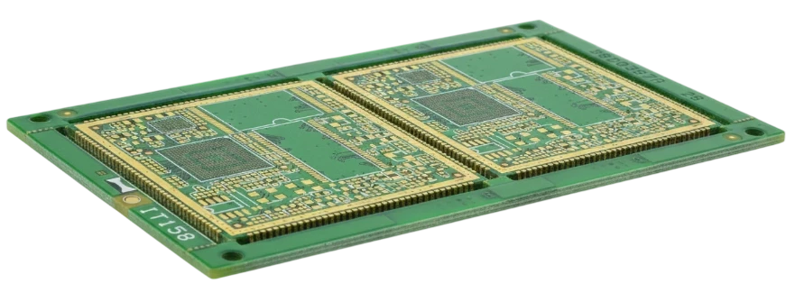
Among the hundreds of laminate formulations recognized across the global electronics supply chain, FR-4 remains the undisputed standard. From low-cost consumer gadgets to multi-layer industrial automation controllers, more than 80% of all rigid printed circuit boards rely on this composite material.
Yet treating the FR4 material as a single generic commodity is one of the most common causes of high-temperature delamination, solder joint fatigue, and signal degradation. Modern FR-4 encompasses a wide family of epoxy resin systems, glass weave architectures, and flame-retardant chemistries with vastly different performance boundaries.
This engineering guide delivers an exhaustive breakdown of FR4 material properties, compares datasheet parameters across standard, mid-Tg, and high-Tg grades, and outlines when your stackup requires an upgrade.
Key takeaways
- What FR-4 means: "FR" stands for Flame Retardant, and "4" designates woven glass-reinforced epoxy resin adhering to NEMA LI 1-1998 and UL94 V-0 flammability standards.
- FR4 dielectric constant (Dk): Typically ranges from 4.2 to 4.7 at 1 GHz, decreasing as signal frequency increases. Dk varies depending on the glass-to-resin ratio (e.g., 7628 heavy glass vs. 1080 light glass).
- Thermal thresholds (Tg, Td): Standard FR-4 features a glass transition temperature ($T_g$) of $130\text{–}140^\circ\text{C}$, mid-$T_g$ sits at $150^\circ\text{C}$, and high-$T_g$ reaches $170\text{–}180^\circ\text{C}$. High-$T_g$ formulations provide essential margins for lead-free reflow ($260^\circ\text{C}$).
- Coefficient of Thermal Expansion (CTE): In the Z-axis (thickness), standard FR-4 expands at approximately $50\text{–}70\text{ ppm/}^\circ\text{C}$ below $T_g$, jumping to $250\text{–}300\text{ ppm/}^\circ\text{C}$ above $T_g$.
- Mechanical & physical metrics: FR-4 has a typical density of $1.85\text{ g/cm}^3$, Young's modulus of 22–24 GPa, and modest thermal conductivity of $0.25\text{–}0.35\text{ W/m}\cdot\text{K}$.
What is FR-4? Composition and grades
The term FR4 pcb material defines a composite structure combining two foundational ingredients:
- Woven fiberglass cloth: E-glass yarn woven into standardized fabrics (such as styles 106, 1080, 2116, 3313, and 7628) provides mechanical tensile strength, flexural rigidity, and dimensional stability.
- Epoxy resin matrix: A thermosetting polymer infused with brominated or halogen-free flame retardants and inorganic ceramic fillers that insulates electrical conductors and bonds copper foil.
Because glass has a high dielectric constant ($Dk \approx 6.0$) and low CTE, while pure cured epoxy has a lower Dk ($Dk \approx 3.2$) and high CTE, the exact ratio of resin-to-glass dictates the mechanical and electrical properties of every specific prepreg and core laminate layer.
Common FR-4 grades in industry
- Standard Tg FR-4 ($T_g \approx 135^\circ\text{C}$): Traditional formulations for tin-lead (SnPb) wave and mild single-pass reflow. Not recommended for modern lead-free cycles.
- Mid-Tg FR-4 ($T_g \approx 150^\circ\text{C}$): The modern entry-level workhorse (e.g., Kingboard KB-6160), fully compatible with RoHS lead-free soldering on 2 to 6 layer boards.
- High-Tg FR-4 ($T_g \ge 170^\circ\text{C}$): Formulations (e.g., Shengyi S1000-2, Isola 370HR) engineered for high-layer counts (8+ layers), thick copper, and repeated thermal cycling.
- Halogen-Free FR-4: Replaces bromine with phosphorus compounds, reducing toxic emissions in consumer portable and green certifications.
FR4 material properties datasheet at a glance
The following engineering datasheet table summarizes the critical electrical, thermal, and mechanical parameters of verified pcb fr4 material grades tested under IPC-TM-650 methods:
| Property | Test Method / Condition | Standard FR-4 (Tg 135) | Mid-Tg FR-4 (Tg 150) | High-Tg FR-4 (Tg 170+) | Units |
|---|---|---|---|---|---|
| Glass Transition Temp ($T_g$) | DSC / TMA | 135 | 150 | 170–180 | $^\circ\text{C}$ |
| Decomposition Temp ($T_d$) | TGA (5% weight loss) | 305 | 320 | 340–350 | $^\circ\text{C}$ |
| Time to Delamination (T260) | TMA | 5–10 | 15–20 | > 30–60 | minutes |
| Time to Delamination (T288) | TMA | 0–2 | 2–5 | 10–15 | minutes |
| Dielectric Constant (Dk @ 1 GHz) | IPC-TM-650 2.5.5.9 | 4.40–4.60 | 4.30–4.45 | 4.10–4.35 | — (dimensionless) |
| Dielectric Constant (Dk @ 10 GHz) | IPC-TM-650 2.5.5.5 | 4.10–4.30 | 4.05–4.20 | 3.90–4.10 | — (dimensionless) |
| Dissipation Factor (Df @ 1 GHz) | IPC-TM-650 2.5.5.9 | 0.020 | 0.016 | 0.012–0.015 | — |
| Dissipation Factor (Df @ 10 GHz) | IPC-TM-650 2.5.5.5 | 0.025 | 0.020 | 0.015–0.018 | — |
| Z-Axis CTE (Below $T_g$) | TMA ($30\text{–}130^\circ\text{C}$) | 60–75 | 50–65 | 40–50 | $\text{ppm/}^\circ\text{C}$ |
| Z-Axis CTE (Above $T_g$) | TMA ($> T_g$) | 280–320 | 250–290 | 200–240 | $\text{ppm/}^\circ\text{C}$ |
| Total Z-Axis Expansion ($50\text{–}260^\circ\text{C}$) | TMA | 4.5–5.5% | 3.5–4.2% | 2.5–3.0% | % expansion |
| X/Y-Axis CTE | TMA | 14–17 | 13–16 | 12–15 | $\text{ppm/}^\circ\text{C}$ |
| Thermal Conductivity ($k$) | Hot-wire / Flash | 0.25 | 0.30 | 0.35–0.40 | $\text{W/m}\cdot\text{K}$ |
| Density ($\rho$) | ASTM D792 | 1.85 | 1.85 | 1.85–1.90 | $\text{g/cm}^3$ |
| Young's Modulus ($E$) | ASTM D638 | 22 | 23 | 24–26 | $\text{GPa}$ |
| Poisson's Ratio ($\nu$) | Static tension | 0.14 | 0.14 | 0.14 | — |
| Dielectric Breakdown Voltage | IPC-TM-650 2.5.6 | > 40 | > 45 | > 50 | $\text{kV/mm}$ |
| Water Absorption | 24h immersion @ $23^\circ\text{C}$ | 0.20% | 0.15% | 0.10% | % weight |
Electrical performance: FR4 dielectric constant and loss
Understanding the dielectric constant of FR-4 is vital for controlled impedance routing:
1. Dk variations by glass style
Lightweight prepregs with high resin content (such as style 106, ~75% resin) exhibit a lower Dk ($Dk \approx 3.8\text{–}4.0$). Conversely, heavy core laminates with tight glass weaves (such as style 7628, ~43% resin) display a significantly higher Dk ($Dk \approx 4.6\text{–}4.7$). Circuit designers must always calculate trace impedance using the specific prepreg/core stackup approved by the PCB manufacturer, rather than assuming an arbitrary average of 4.5.
2. High-frequency attenuation
With a dissipation factor ($\text{Df} \approx 0.015\text{–}0.020$), standard FR-4 dissipates significant signal energy into dielectric heating above 3–5 GHz. For PCIe 4.0/5.0, 10G+ Ethernet, or RF microwave designs, upgrading to low-loss mid-Dk materials (such as Panasonic Megtron 6 or Rogers RO4350B) prevents excessive eye-diagram closure.
Thermal properties: Tg, Td, and CTE
Reliability failures during lead-free assembly and thermal cycling trace back to three thermal properties:
Glass Transition Temperature ($T_g$)
The glass transition temperature marks the temperature where the cured polymer chains transition from a rigid glassy state into a softer rubbery state. Below $T_g$, the material expands modestly. Once temperature exceeds $T_g$, expansion accelerates by 400% to 500%.
Z-Axis CTE and PTH barrel reliability
Copper has a CTE of $17 \text{ ppm/}^\circ\text{C}$. In the planar X and Y directions, FR-4's woven glass fibers restrain expansion to $12\text{–}16 \text{ ppm/}^\circ\text{C}$, closely matching copper. However, along the vertical Z-axis, there are no glass fibers to restrain expansion.
During $260^\circ\text{C}$ lead-free reflow, standard FR-4 expands vertically by 4.5% to 5.5%, whereas copper foil expands by less than 0.5%. This severe mechanical mismatch places immense tensile strain on plated through-hole (PTH) barrels, leading to barrel cracking, corner knee fractures, and inner-layer via separation. Specifying high-Tg FR-4 suppresses total Z-expansion below 3.0%, ensuring survivability across multiple thermal shock cycles.
Decomposition Temperature ($T_d$)
$T_d$ represents the point where the polymer chemically breaks down and loses 5% of its original mass. Standard FR-4 begins irreversible degradation around $305^\circ\text{C}$, whereas high-reliability formulations reach $340\text{–}350^\circ\text{C}$, providing safe process windows during manual soldering rework.
Mechanical characteristics: Density, Young's modulus, and stiffness
- FR4 density: Measures approximately $1.85\text{ g/cm}^3$ (or $0.067\text{ lb/in}^3$). For weight-sensitive aerospace avionics or handheld drones, multilayer FR-4 weight can be predicted directly from board volume and copper ounce weights.
- Flexural strength & Young's Modulus: With an elastic modulus of $22\text{–}26\text{ GPa}$, FR-4 delivers exceptional stiffness that resists board sagging under heavy transformers and inductors.
- Thermal conductivity: Standard FR-4 is a thermal insulator ($k \approx 0.3 \text{ W/m}\cdot\text{K}$). High-power LED arrays and motor drive stages require thermal vias, heavy copper planes, or transition to aluminum metal-core PCBs (MCPCBs) to shed heat.
When is FR-4 not enough?
While FR4 PCB manufacturing accommodates the vast majority of applications, designers must move beyond standard FR-4 when:
- Layer count exceeds 8–10 layers: Total Z-axis expansion strains high-aspect-ratio vias during lead-free soldering. Upgrade to high-Tg FR-4 ($T_g \ge 170^\circ\text{C}$, IPC-4101/126).
- Signal speeds exceed 10 Gbps: High Df causes severe channel insertion loss. Migrate to mid-loss or ultra-low-loss laminates (e.g., Megtron 6).
- Continuous operating temperature exceeds $130^\circ\text{C}$: Under-hood automotive and downhole oil-and-gas electronics demand polyimide substrates ($T_g > 250^\circ\text{C}$).
- RF/Microwave frequencies exceed 3 GHz: Antennas and phased arrays demand tightly controlled Dk tolerances ($\pm 0.05$) found only in hydrocarbon/ceramic or PTFE laminates.
Calling out FR-4 in an RFQ / Fabrication Drawing
Avoid writing vague notes like "Material: FR-4" on your fabrication print. To ensure reproducible quality from board houses:
- Specify IPC-4101 slash sheets: Call out
IPC-4101/126for High-Tg lead-free FR-4, orIPC-4101/21for standard mid-Tg FR-4. - State thermal limits: Explicitly mandate
$T_g \ge 170^\circ\text{C}$, $T_d \ge 340^\circ\text{C}$, and $T288 \ge 10\text{ min}$. - Specify UL 94 V-0 flammability: Ensure the fabricator applies an authorized UL marking with recognized CTI ratings (Comparative Tracking Index > 175 V or PLC 3).
Frequently Asked Questions
Q: What is the dielectric constant of FR4 material? A: The dielectric constant (Dk) of FR4 material typically ranges between 4.2 and 4.7 at 1 GHz. Because FR-4 is a composite of glass and epoxy resin, the exact Dk depends on the glass weave style, resin percentage, and signal frequency.
Q: What is the difference between FR-4 Tg 150 and Tg 170? A: FR-4 Tg 150 is a mid-Tg formulation designed for standard 2 to 6 layer lead-free boards. FR-4 Tg 170 is a high-Tg material engineered with greater cross-linking density, delivering lower Z-axis expansion and superior thermal endurance for high-layer count (8+ layer) and automotive applications.
Q: What is the density of FR4? A: The density of standard FR-4 is approximately $1.85\text{ g/cm}^3$ ($1850\text{ kg/m}^3$), which is about 20% lighter than aluminum and significantly lighter than copper ($8.96\text{ g/cm}^3$).
Q: What is the thermal conductivity of FR-4? A: FR-4 has poor thermal conductivity, typically between $0.25$ and $0.35\text{ W/m}\cdot\text{K}$. To dissipate heat from power components on FR-4 boards, designers rely on thermal via arrays, thick copper pours (2–3 oz), or external heat sinks.
Q: Is FR4 flame retardant? A: Yes. The "FR" in FR-4 stands for Flame Retardant. FR-4 laminates are certified to UL94 V-0 flammability, meaning flaming combustion extinguishes within 10 seconds on vertical specimens without dripping flaming particles.