
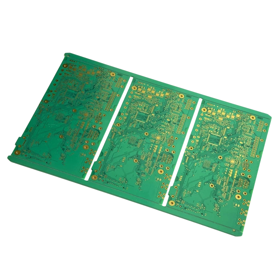
When an assembled printed circuit board travels through a lead-free reflow oven, peak temperatures reach $250^\circ\text{C}$ to $260^\circ\text{C}$. At these elevated temperatures, the epoxy resin binding the board's copper layers and glass fibers undergoes a profound physical transformation. Understanding this transformation—and the specific thermal boundary where it occurs—is the study of glass transition temperature (Tg).
Selecting an inappropriate Tg for your board leads directly to barrel cracking in plated through-holes (PTH), inner-layer pad delamination, and warpage that misaligns fine-pitch BGA packages.
This engineering guide explains what glass transition temperature means in polymer science, how Tg is measured in PCB manufacturing, how it interacts with Td and CTE, and when to specify high-Tg materials for mission-critical reliability.
Key takeaways
- Glass transition temperature definition: Tg is the critical temperature range where an amorphous polymer transitions from a hard, glassy, rigid state into a soft, flexible, rubbery state.
- Not a melting point: The glass transition temperature is not melting; the resin does not liquefy. It is a reversible thermodynamic shift in molecular chain mobility and volume expansion.
- Z-axis CTE surge: Above Tg, a laminate's vertical thermal expansion rate increases by 400% to 500% (jumping from ~50 ppm/°C to ~260 ppm/°C), placing massive tensile strain on copper via barrels.
- Industry classifications: Standard FR-4 ($T_g \approx 130\text{–}140^\circ\text{C}$), Mid-$T_g$ ($T_g \approx 150^\circ\text{C}$), and High-$T_g$ ($T_g \ge 170^\circ\text{C}$).
- When to upgrade: High-$T_g$ laminates are mandatory for multilayer boards with 8 or more layers, lead-free RoHS reflow assemblies ($260^\circ\text{C}$ peak), thick copper power planes (≥ 2 oz), and automotive or industrial operating environments exceeding $100^\circ\text{C}$.
What is glass transition temperature? Definition and physics
To explain glass transition temperature in polymer science, we look at molecular chain kinetics. Cured epoxy resin in a PCB substrate is a highly cross-linked amorphous polymer network. At room temperature, the polymer chains are locked in place, vibrating only slightly. The material is mechanically stiff and dimensionally stable.
As thermal energy increases, the molecular chains gain kinetic energy until they overcome internal intermolecular barriers and begin sliding past one another. The temperature point at which this transition begins is the glass transition temperature ($T_g$).
When people ask "what does glass transition temperature mean" or "glass transition temperature meaning in engineering," it refers to:
- A dramatic decrease in mechanical stiffness (Young's modulus drops by up to 90%).
- A sharp acceleration in thermal expansion (CTE jumps 4x to 5x).
- A decline in dielectric breakdown strength and insulation resistance.
The glass transition is a second-order thermodynamic transition, meaning it occurs across a transition window of $5^\circ\text{C}$ to $15^\circ\text{C}$ rather than at a sharp, single melting point.
How is Tg measured? (DSC, TMA, DMA)
Laminate manufacturers and PCB qualification laboratories determine the glass transition temperature using three standardized test methods defined under IPC-TM-650:
| Measurement Method | IPC Test Standard | Physical Property Monitored | Relative Tg Value | Application / Notes |
|---|---|---|---|---|
| Differential Scanning Calorimetry (DSC) | IPC-TM-650 2.4.25 | Change in heat capacity ($\Delta C_p$) | Baseline ($T_g$) | Most common method on standard laminate datasheets |
| Thermomechanical Analysis (TMA) | IPC-TM-650 2.4.24 | Dimensional change (Z-axis deflection) | Typically $2\text{–}5^\circ\text{C}$ lower than DSC | Standard for calculating Z-CTE and delamination times (T260/T288) |
| Dynamic Mechanical Analysis (DMA) | IPC-TM-650 2.4.24.4 | Loss modulus / $\tan(\delta)$ damping peak | Typically $5\text{–}10^\circ\text{C}$ higher than DSC | Most sensitive; preferred for high-frequency and advanced composite polymers |
When comparing supplier datasheets, always confirm whether Tg was measured via DSC or TMA, as differences in methodology can shift reported numbers by several degrees Celsius.
Tg vs Td vs Time to Delamination (T260 / T288)
A common engineering mistake is assuming that a high Tg laminate automatically guarantees extreme thermal resistance. In reality, a board's survivability under lead-free soldering depends on a triad of thermal metrics:
1. Glass Transition Temperature ($T_g$)
Defines the onset of accelerated mechanical expansion. A higher Tg delays the onset of severe Z-axis strain.
2. Decomposition Temperature ($T_d$)
The temperature at which the resin chemically breaks down and loses 5% of its mass due to thermal degradation (tested via Thermogravimetric Analysis, TGA). A material can possess a high Tg ($170^\circ\text{C}$) but a low Td ($300^\circ\text{C}$), rendering it fragile during manual solder rework. Reliable lead-free laminates require $T_d \ge 340^\circ\text{C}$.
3. Time to Delamination (T260 and T288)
Measures how many minutes a cured laminate can withstand continuous exposure to $260^\circ\text{C}$ or $288^\circ\text{C}$ before internal delamination or blister separation occurs:
- Standard FR-4 typically fails T260 within 5 to 10 minutes and T288 in under 2 minutes.
- Premium High-Tg FR-4 survives T260 for over 30 to 60 minutes and T288 for 10 to 15 minutes.
Why Tg matters in lead-free assembly
The global transition to RoHS-compliant lead-free solder (SAC305, Sn-Ag-Cu) drove the widespread adoption of high-Tg laminates.
Traditional tin-lead solder (Sn63Pb37) reflows at a peak temperature of $215^\circ\text{C}$ to $225^\circ\text{C}$. Under these mild conditions, standard FR-4 ($T_g \approx 135^\circ\text{C}$) spends very little time above its transition point.
In contrast, lead-free solders melt at $217^\circ\text{C}$, requiring oven peak temperatures of $245^\circ\text{C}$ to $260^\circ\text{C}$. If a board is fabricated with standard $135^\circ\text{C}$ FR-4, the laminate spends more than 60 seconds deep in its rubbery expansion zone during each reflow pass. In double-sided assemblies undergoing two reflow runs plus wave soldering, cumulative barrel strain causes:
- Barrel cracking: Radial fractures around the copper via wall.
- Corner knee cracks: Tensile fracture at the junction where the surface capture pad meets the plated hole barrel.
- Pad cratering: Micro-cracking in the resin immediately beneath high-stress BGA solder joints.
Upgrading to high-Tg resin ($T_g \ge 170^\circ\text{C}$) reduces cumulative Z-axis expansion during the reflow profile from over 5.0% down to less than 2.8%, preserving via integrity.
Standard vs Mid vs High Tg: Selection matrix
The table below provides engineering guidelines for choosing the correct Tg grade based on project complexity:
| Parameter / Requirement | Standard Tg (130–140°C) | Mid Tg (150°C) | High Tg (170°C+) |
|---|---|---|---|
| Typical Layer Count | 1 to 4 layers | 4 to 6 layers | 8 to 32+ layers |
| Soldering Process | Tin-lead (SnPb) only | Single-pass lead-free | Multi-pass lead-free & selective solder |
| Board Thickness | $\le 1.6\text{ mm}$ | $\le 2.0\text{ mm}$ | $> 2.0\text{ mm}$ (high aspect ratio) |
| Copper Weight | 0.5 oz to 1.0 oz | 1.0 oz to 2.0 oz | $\ge 2.0\text{ oz}$ (heavy copper) |
| Operating Temperature | $< 80^\circ\text{C}$ | $< 100^\circ\text{C}$ | Continuous $105\text{–}130^\circ\text{C}$ |
| IPC-4101 Slash Sheet | IPC-4101/21 | IPC-4101/24, /99 | IPC-4101/126, /129 |
| Common Laminates | Generic FR-4 | KB-6160, Ventec VT-481 | Shengyi S1000-2, Isola 370HR |
For demanding power electronics and multi-layer stacks, explore APTPCB's certified high Tg PCB manufacturing services.
How to specify Tg on your fabrication drawing
To avoid ambiguity during quoting and CAM engineering:
- Specify exact numerical thresholds: Write
Material: FR-4 with Tg >= 170°C (DSC), Td >= 340°C (TGA), T288 >= 10 min. - Mandate IPC slash sheets: Call out
Material shall conform to IPC-4101/126 or approved equivalent. - Avoid generic phrases: Do not simply state "High-Tg material required"; specify whether you require RoHS lead-free compliance and whether halogen-free formulation is mandated.
Frequently Asked Questions
Q: What is a glass transition temperature in simple words? A: Glass transition temperature (Tg) is the temperature point where an amorphous polymer changes from a hard, glassy material into a softer, rubbery state.
Q: Is Tg the same as melting point? A: No. Cured thermoset polymers like PCB epoxy resin do not melt. Tg marks a mechanical and thermodynamic softening point. If heated further beyond its decomposition temperature (Td), the material chemically degrades and chars rather than melts into a liquid.
Q: What is a good Tg for lead-free PCBs? A: For lead-free soldering, a minimum Tg of $150^\circ\text{C}$ (Mid-Tg) is recommended for simple 2 to 4 layer boards. For 6 layers or more, boards with BGA packages, or heavy copper power boards, a Tg of $170^\circ\text{C}$ or higher is strongly advised.
Q: Can a PCB operate above its Tg continuously? A: No. Continuous operation above Tg accelerates thermal aging, softens dielectric support for traces, lowers dielectric breakdown strength, and induces severe CTE expansion that fractures vias over time. The continuous operating temperature of a board should remain at least $20\text{–}30^\circ\text{C}$ below its Tg.
Q: How does Tg affect board warpage? A: Materials with higher Tg retain their structural modulus to higher temperatures during reflow. This prevents excessive sagging, bow, and twist, ensuring coplanarity for fine-pitch BGA and QFN component soldering.