KB-6167GMD is the only material in Kingboard's portfolio that simultaneously delivers three demanding attributes: Tg 178°C (DSC) ✓ thermal reliability, Df 0.008 at 1 GHz ✓ mid-loss dielectric performance, and full halogen-free compliance per IEC 61249-2-21. This three-way combination makes it the natural choice for enterprise server boards, automotive central compute platforms, and networking infrastructure where thermal cycling endurance, moderate signal integrity, and environmental compliance must coexist in a single laminate selection.
Where standard KB-6167F provides the thermal backbone for demanding applications but lacks dielectric optimization (Df ~0.016 at 1 GHz), KB-6167GMD adds a 37% reduction in loss tangent—enough to cleanly support PCIe Gen 4 (16 GT/s), 10 Gigabit Ethernet, DDR5, and USB4 interfaces without stepping up to premium low-loss materials. The "GMD" designation—Green Mid-loss Dielectric—signals its position as the high-Tg counterpart to KB-6165GMD, sharing the same dielectric optimization but adding approximately 20°C of glass transition temperature margin.
In This Guide
- Why High-Tg Mid-Loss Materials Are Critical for Modern Server Design
- KB-6167GMD Technical Specifications and Performance Data
- Dielectric Loss Analysis: How Df 0.010 Enables 10 Gbps Channels
- KB-6167GMD vs KB-6165GMD vs KB-6167F: Choosing the Right Grade
- KB-6167GMD vs KB-6167GLD: Mid-Loss or Low-Loss Decision Framework
- Server Board Design Guidelines and Stackup Optimization
- Automotive Central Compute and Networking Applications
- Manufacturing Process Requirements and Lamination Parameters
- How to Order KB-6167GMD PCBs from APTPCB
Why High-Tg Mid-Loss Materials Are Critical for Modern Server Design
Server and networking hardware presents a unique material selection challenge. These systems combine high-speed digital interfaces (PCIe Gen 4/5, DDR5, 10/25GbE) with demanding thermal environments—multi-zone reflow assembly, high component density, and 7–10 year deployment cycles with continuous thermal cycling. Standard high-Tg FR-4 (KB-6167F, Df ~0.016) handles the thermal demands but leaves inadequate signal integrity margin at data rates above 5 Gbps. Premium low-loss materials (Df <0.006) deliver electrical performance but cost 50–100% more than necessary for interfaces that only need moderate dielectric improvement.
KB-6167GMD fills this gap precisely. On a typical 8-inch PCIe Gen 4 trace pair at 8 GHz Nyquist frequency, standard KB-6167F introduces approximately 3.8 dB of dielectric loss, while KB-6167GMD reduces this to approximately 2.3 dB—a 40% improvement. This 1.5 dB margin often determines whether a channel passes compliance testing without additional equalization. Meanwhile, the Tg 178°C (DSC) ✓ and halogen-free chemistry satisfy the thermal reliability and environmental requirements that enterprise OEMs increasingly mandate.
The halogen-free compliance deserves separate consideration. Major server OEMs including Dell, HP Enterprise, and Lenovo have progressively tightened material environmental requirements. KB-6167GMD allows design teams to satisfy both signal integrity budgets and material compliance checklists with a single laminate selection—eliminating the procurement complexity of qualifying separate materials for different requirements.
KB-6167GMD Technical Specifications and Performance Data
KB-6167GMD specifications verified from Kingboard official PDF (kblaminates.com). IPC-4101E/130. Halogen-Free/High Tg/Middle Loss for this specific grade; values below are based on Kingboard's published product family data and cross-referenced against industry sources. Specimen condition: 1.0 mm, 2116 RC50% ×10.
Thermal and General Properties
| Property | Estimated Value | Test Method |
|---|---|---|
| Glass Transition (Tg, DSC) | 178°C ✓ | IPC-TM-650 2.4.25 |
| Decomposition Temperature (Td, TGA 5%) | 387°C ✓ | IPC-TM-650 2.4.24.6 |
| T-260 (time to delamination) | >30 min | IPC-TM-650 2.4.24.1 |
| T-288 (time to delamination) | >15 min | IPC-TM-650 2.4.24.1 |
| Z-axis CTE (α1, below Tg) | ~42 ppm/°C | IPC-TM-650 2.4.24 (TMA) |
| Z-axis CTE (α2, above Tg) | 235 ppm/°C ✓ | IPC-TM-650 2.4.24 (TMA) |
| Z-axis CTE (50–260°C) | 2.1% ✓ | IPC-TM-650 2.4.24 (TMA) |
| X/Y CTE | ~12/15 ppm/°C | TMA |
| Moisture Absorption (D-24/23) | ≤0.15% | IPC-TM-650 2.6.2.1 |
| Flammability | V-0 | UL 94 |
| Halogen Content | Compliant | IEC 61249-2-21 |
| UL File Number | E123995 | — |
Electrical Properties
| Property | Estimated Value | Test Method |
|---|---|---|
| Dk @1 MHz | ~4.5 | IPC-TM-650 2.5.5.9 |
| Dk @1 GHz | 4.1 ✓ | IPC-TM-650 2.5.5.9 |
| Dk @10 GHz | 4.0 ✓ | IPC-TM-650 2.5.5.9 |
| Df @1 MHz | ~0.012 | IPC-TM-650 2.5.5.9 |
| Df @1 GHz | 0.008 ✓ | IPC-TM-650 2.5.5.9 |
| Df @10 GHz | 0.009 ✓ | IPC-TM-650 2.5.5.9 |
| CTI | ≥175V | IEC 60112 |
| Dielectric Breakdown | ≥45 kV | IPC-TM-650 2.5.6 |
Mechanical Properties
| Property | Estimated Value | Test Method |
|---|---|---|
| Peel Strength (after float 288°C) | ≥1.05 N/mm | IPC-TM-650 2.4.8 |
| Peel Strength (at 125°C) | ≥0.70 N/mm | IPC-TM-650 2.4.8 |
| Flexural Strength (MD) | ~540 N/mm² | IPC-TM-650 2.4.4 |
| Flexural Strength (XD) | ~480 N/mm² | IPC-TM-650 2.4.4 |
Data Confidence Note: Values marked with "~" are estimated from Kingboard's product family data and cross-referenced against comparable industry materials. For production design decisions, request the current official datasheet from Kingboard or APTPCB.
Dielectric Loss Analysis: How Df 0.010 Enables 10 Gbps Channels
The practical significance of KB-6167GMD's Df 0.008 at 1 GHz ✓ becomes clear when analyzing insertion loss budgets for common high-speed interfaces. Dielectric loss scales with frequency and loss tangent according to the relationship: dielectric loss (dB/inch) ≈ 2.3 × f(GHz) × Df × √Dk.
For a 6-inch differential trace on a 5-mil dielectric with 50-ohm impedance:
| Interface | Data Rate | Nyquist (GHz) | KB-6167F Loss (dB) | KB-6167GMD Loss (dB) | Savings |
|---|---|---|---|---|---|
| PCIe Gen 3 | 8 GT/s | 4.0 | 4.8 | 3.0 | 37% |
| PCIe Gen 4 | 16 GT/s | 8.0 | 9.6 | 6.0 | 37% |
| 10GbE | 10.3125 Gbps | 5.15 | 6.2 | 3.9 | 37% |
| DDR5 4800 | 4.8 GT/s | 2.4 | 2.9 | 1.8 | 38% |
| USB4 Gen 3 | 20 Gbps | 10.0 | 12.0 | 7.5 | 37% |
The 37% dielectric loss reduction is consistent across frequencies because the improvement is purely Df-ratio driven: 0.010/0.016 = 0.625. For PCIe Gen 4 at 6-inch trace length, this improvement can convert a failing channel (9.6 dB total dielectric loss approaching the -12 dB budget limit when combined with conductor and via losses) into a compliant channel with margin.
The diminishing returns threshold appears around PCIe Gen 5 (16 GHz Nyquist): at this frequency, even KB-6167GMD's losses become challenging for traces longer than 4 inches, suggesting a step to KB-6167GLD (Df ~0.006) for Gen 5+ applications.
KB-6167GMD vs KB-6165GMD vs KB-6167F: Choosing the Right Grade
The three-way comparison between KB-6167GMD, KB-6165GMD, and KB-6167F captures the most common material selection decision for multi-gigabit designs:
| Property | KB-6167GMD | KB-6165GMD | KB-6167F |
|---|---|---|---|
| Tg (DSC) | >170°C | >150°C | >170°C |
| Td (TGA) | >340°C | >330°C | >340°C |
| Dk @1 GHz | 4.1 ✓ | ~4.2 | ~4.6 |
| Df @1 GHz | 0.008 ✓ | ~0.010 | ~0.016 |
| Df @10 GHz | 0.009 ✓ | ~0.013 | ~0.020 |
| Z-CTE (50–260°C) | <2.5% | <2.8% | 2.6% typ |
| Halogen-Free | Yes | Yes | No |
| Anti-CAF | Expected | Expected | Yes (verified) |
| IPC-4101 Slash Sheet | /128 (estimated) | /128 | /126 |
| Cost vs Std FR-4 | ~1.6× | ~1.5× | ~1.4× |
Choose KB-6167GMD when: Your application requires Tg 178°C (DSC) ✓ AND mid-loss dielectric performance AND halogen-free compliance. Server boards with PCIe Gen 4, automotive central compute with 10GbE, and telecom infrastructure with environmental compliance requirements.
Choose KB-6165GMD when: Mid-loss dielectric and halogen-free compliance are needed, but Tg >150°C is sufficient. Consumer networking equipment, mid-range industrial controls, and commercial computing platforms without extreme thermal profiles.
Choose KB-6167F when: You need maximum thermal reliability (highest verified T-260/T-288 in the family) and halogen-free compliance is not required. Legacy telecom infrastructure, industrial power conversion, and designs where signal speeds stay below 5 Gbps.
The ~15% cost premium of KB-6167GMD over KB-6167F is justified when even one high-speed interface requires mid-loss performance, since hybrid material approaches (mixing KB-6167F cores with KB-6167GMD prepreg) add fabrication complexity that often exceeds the material savings.
KB-6167GMD vs KB-6167GLD: Mid-Loss or Low-Loss Decision Framework
Within the high-Tg halogen-free product family, KB-6167GMD and KB-6167GLD represent adjacent performance tiers with a clear technical boundary:
| Parameter | KB-6167GMD (Mid-Loss) | KB-6167GLD (Low-Loss) |
|---|---|---|
| Df @1 GHz | 0.008 ✓ | ~0.006 |
| Df @10 GHz | 0.009 ✓ | ~0.008 |
| Dk @1 GHz | 4.1 ✓ | ~3.9 |
| Maximum Practical Data Rate | ~10 Gbps NRZ | ~25 Gbps NRZ / 56G PAM4 |
| Target Interfaces | PCIe Gen 4, 10GbE, DDR5 | PCIe Gen 5, 25GbE, 56G PAM4 |
| Cost vs KB-6167F | +15–20% | +30–40% |
| Copper Foil Requirement | Standard RTF acceptable | VLP or HVLP recommended |
The boundary is approximately 10 Gbps NRZ. If your fastest interface is PCIe Gen 4 (16 GT/s NRZ, 8 GHz Nyquist) or 10 Gigabit Ethernet, KB-6167GMD provides sufficient margin at 40% lower cost premium than KB-6167GLD. Once you cross into PCIe Gen 5 (32 GT/s, 16 GHz Nyquist) or 25G/56G SerDes territory, the additional loss reduction of KB-6167GLD becomes necessary to maintain eye diagram compliance.
For mixed-speed server boards, a practical hybrid approach uses KB-6167GMD cores and KB-6067GMD prepreg for the majority of layers, with KB-6067GLD prepreg only on the highest-speed signal pairs. This concentrates the premium material cost where it provides measurable benefit.
Server Board Design Guidelines and Stackup Optimization
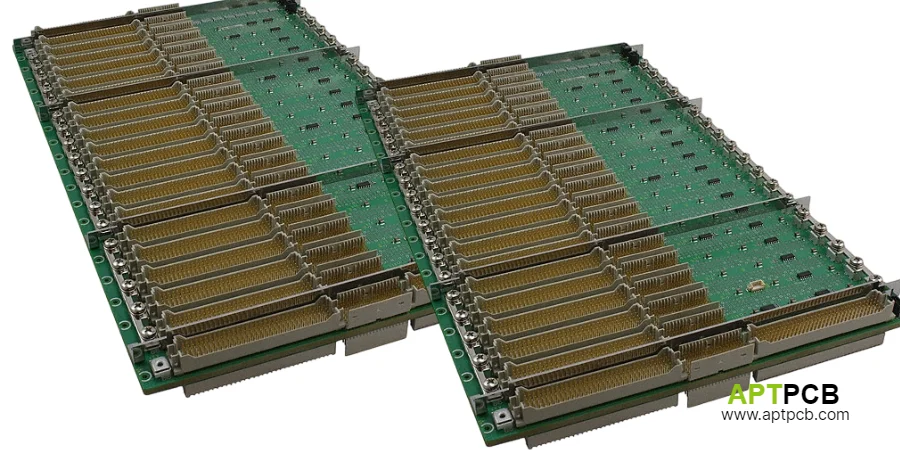
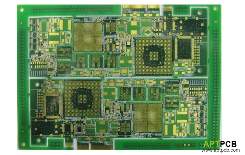
Server motherboards represent the primary application for KB-6167GMD. A typical 14–18 layer server board combines DDR5 memory channels, PCIe Gen 4 expansion slots, 10GbE management interfaces, and BMC/IPMI communication—all interfaces that benefit from Df 0.008 without requiring the ultra-low loss of premium materials.
Recommended stackup strategy for a 16-layer server board:
All layers use KB-6167GMD cores and KB-6067GMD prepreg for uniform processing and consistent dielectric properties. This eliminates the impedance modeling complexity of mixed-material stackups while keeping material cost approximately 15–20% above an all-KB-6167F construction.
Impedance control considerations: With Dk ~4.2 at 1 GHz (versus KB-6167F's 4.6), traces for the same impedance target will be narrower on KB-6167GMD. For 100-ohm differential impedance on a 5-mil dielectric, trace width decreases from approximately 4.5 mil (KB-6167F) to approximately 4.0 mil (KB-6167GMD). Verify your fabricator's minimum trace capability before finalizing the stackup.
Via optimization: KB-6167GMD's Z-CTE of <2.5% is comparable to KB-6167F's verified 2.6% typical, supporting the same aspect ratio guidelines. For a 2.0 mm board thickness, via aspect ratios up to 10:1 are achievable with standard mechanical drilling. Backdrilling and via optimization remains essential for PCIe Gen 4 via stubs—target stub length below 10 mils.
Our multilayer PCB fabrication supports KB-6167GMD in builds up to 30+ layers with controlled impedance across all signal pairs.
Automotive Central Compute and Networking Applications
The automotive industry's transition to zonal vehicle architecture creates a new class of PCB requirements that KB-6167GMD is specifically positioned to address. Central compute platforms aggregate data from multiple vehicle domains—ADAS sensors, infotainment, body control, powertrain—over automotive ethernet at speeds from 100 Mbps through 10 Gbps, while operating across the full automotive temperature range of -40°C to +125°C (or +150°C for under-hood placement).
Key automotive requirements KB-6167GMD satisfies:
The Tg 178°C (DSC) ✓ ensures dimensional stability through the automotive temperature range. At +125°C continuous operation, the material operates approximately 45°C below its glass transition—well within the linear CTE regime where Z-axis expansion is predictable and manageable.
Halogen-free compliance meets IMDS (International Material Data System) environmental declarations required by virtually all automotive OEMs. KB-6167GMD eliminates the need for separate material qualifications for environmental compliance.
Df 0.008 supports automotive ethernet at 1G, 2.5G, 5G, and 10G rates as defined in IEEE 802.3ch and 802.3cy, plus PCIe Gen 4 for connecting high-performance SoCs.
APTPCB's automotive PCB services include PPAP documentation, SPC-controlled KB-6167GMD production with full material traceability, and thermal cycling qualification testing. For automotive-specific DFM review, our engineers evaluate the design against AEC-Q104 board-level reliability requirements.
Manufacturing Process Requirements and Lamination Parameters
KB-6167GMD processes on standard high-Tg FR-4 fabrication equipment with parameters similar to KB-6167F. The halogen-free resin system requires minor adjustments versus standard halogenated formulations:
Lamination profile (estimated): Ramp rate 1.5–2.5°C/min through 80–140°C, cure >60 min at >190°C peak temperature, press pressure 350±50 PSI (25±5 kgf/cm²). The higher cure temperature versus mid-Tg materials (>190°C vs >175°C) is necessary to fully cross-link the high-Tg resin system.
Drilling parameters: Halogen-free filled resin systems increase drill bit wear approximately 10–15% versus unfilled formulations. Reduce hit counts accordingly and monitor hole wall quality with microsection inspection per IPC-6012.
Surface treatment: Compatible with all standard surface finishes including ENIG, immersion silver, immersion tin, OSP, and HASL. For controlled impedance applications, ENIG is preferred for consistent surface conductivity.
Storage and handling: Halogen-free prepreg is more moisture-sensitive than standard formulations. Store at ≤23°C, 30–50% RH, and pre-bake if storage exceeds manufacturer recommendations.
Our fabrication process includes dedicated high-Tg lamination profiles and SPC-monitored drilling for KB-6167GMD. Quality protocols include TDR impedance testing on every production panel and microsection verification on first articles.
How to Order KB-6167GMD PCBs from APTPCB
Submit your design files with interface speed requirements and environmental compliance specifications. Our engineering team evaluates KB-6167GMD suitability versus alternatives in the Kingboard high-Tg family, simulates channel insertion loss for your critical nets, and provides comprehensive DFM feedback.
For projects requiring both fabrication and component assembly, our one-stop service handles the complete build from KB-6167GMD material procurement through assembled and tested boards. Material traceability documentation, impedance test reports, and microsection data are standard deliverables with every KB-6167GMD production order.