Kingboard Holdings is the world's largest manufacturer of copper-clad laminates, and their product portfolio spans over 20 distinct materials—from economy FR-4 for LED driver boards to low-loss substrates for server, backplane, and high-speed computing applications. Choosing the right material from this portfolio directly impacts your PCB's cost, reliability, signal integrity, and environmental compliance. This guide provides a systematic decision framework to navigate Kingboard's product line and select the optimal laminate for your specific application.
The most common material selection mistake is defaulting to "high-Tg FR-4" regardless of actual requirements. This guide helps engineers identify exactly which performance attributes matter for their design—and more importantly, which ones don't—so they can specify the most cost-effective material that meets all genuine requirements without paying for unnecessary capability.
In This Guide
- Five-Step Decision Framework: From Signal Speed to Material Selection
- Tier 1: Standard FR-4 Materials for Consumer and General Electronics (Tg 130–140°C)
- Tier 2: Mid-Tg FR-4 Materials for Industrial and Telecom Applications (Tg 150°C)
- Tier 3: High-Tg FR-4 Materials for Server, Automotive, and Aerospace (Tg 170°C+)
- Tier 4: Mid-Loss and Low-Loss Materials for Multi-Gigabit Signal Integrity
- Tier 5: Specialty Materials Including RF Laminates and Polyimide
- Master Comparison Table: All Kingboard Materials at a Glance
- Cost Optimization Strategies: Hybrid Stackups and Right-Sizing Material Selection
- How APTPCB Helps You Select and Source the Right Kingboard Material
Five-Step Decision Framework: From Signal Speed to Material Selection
Follow these five questions in order. Each answer narrows your material options until the right selection becomes clear:
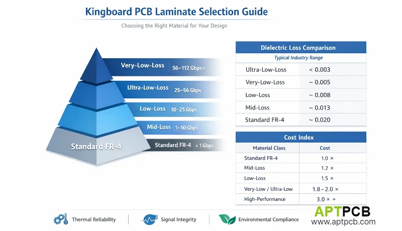
Step 1: What is your fastest signal interface?
- Below 1 Gbps → Standard FR-4 (Tier 1 or 2)
- 1–10 Gbps → Mid-loss material (Tier 4, GMD class)
- 10–25 Gbps → Low-loss material (Tier 4, GLD class)
- 25–56 Gbps → Low-loss (Tier 4, GLD class) or external ultra-low-loss
- 56–112 Gbps → External ultra-low-loss mandatory (Megtron 6/7 class or higher)
Step 2: Does the design require lead-free qualified material?
- No (leaded solder or minimal reflow) → Standard /21 slash sheet OK (KB-6150, KB-6160, KB-6160A)
- Yes (SAC305, multiple reflow) → Need /24, /99, /101, /124, or /126 slash sheets
Step 3: What is the continuous operating temperature?
- Below 100°C → Standard Tg (130–140°C) sufficient
- 100–130°C → Mid-Tg (150°C) recommended
- 130–150°C → High-Tg (170°C+) required
- Above 150°C → PI-520G (Tg 204°C) or PI-515G required
Step 4: Is halogen-free compliance required?
- No → Standard formulations (KB-6160, KB-6165, KB-6167F)
- Yes → "G" suffix materials (KB-6165G, KB-6165GMD, KB-6167GMD, etc.)
Step 5: What is the board layer count and thickness?
- 1–2 layers, ≤1.6 mm → Standard FR-4 CTE acceptable
- 4–8 layers, 1.0–2.0 mm → Mid-Tg or higher recommended
- 10+ layers, >2.0 mm → Low CTE critical (KB-6164, KB-6167F, KB-6168LE)
Tier 1: Standard FR-4 Materials for Consumer and General Electronics (Tg 130–140°C)
Standard Tg materials serve applications where thermal demands are modest and cost optimization is the primary driver:
| Material | Tg | Key Feature | Primary Use |
|---|---|---|---|
| KB-6150 | 132°C ✓ | Lowest cost | Economy consumer electronics |
| KB-6160 | 135°C ✓ | Full KB-6060 prepreg system | General multilayer production |
| KB-6160A | ~130°C | UVB blocking for double-sided | Two-layer board production |
| KB-6160C | ~140°C | Lead-free qualified (/24) | Lead-free consumer multilayer |
| KB-6160F/KB-6160LC | ~135°C | Filled resin, lower CTE | Low-expansion standard FR-4 |
When to use Tier 1: Consumer electronics, LED lighting, simple IoT, power supplies, peripherals, and any application where operating temperature stays below 100°C and the design doesn't require specific signal integrity optimization.
When to upgrade: If you need Tg above 140°C, anti-CAF resistance, halogen-free compliance, or signal speeds above 1 Gbps, move to Tier 2 or higher. The cost difference between Tier 1 and Tier 2 is typically 15–25%—modest compared to the reliability risk of using an underspecified material.
Tier 2: Mid-Tg FR-4 Materials for Industrial and Telecom Applications (Tg 150°C)
Mid-Tg materials represent the performance center of Kingboard's portfolio—the default choice for applications that exceed consumer-grade requirements but don't need the thermal extremes of high-Tg:
| Material | Tg | Key Feature | Primary Use |
|---|---|---|---|
| KB-6164 | 140°C ✓ | Anti-CAF + low CTE (3.5%) | High-voltage, lead-free, anti-CAF |
| KB-6165 | 153°C ✓ | Unfilled, DICY-free, anti-CAF | General mid-Tg multilayer |
| KB-6165F | 157°C ✓ | Filled resin, lower CTE (3.0%) | Via reliability focused mid-Tg |
| KB-6165C/KB-6165LE | ~150°C | Halogen-free / low expansion | Specialized mid-Tg variants |
| KB-6165G | 155°C ✓ | Halogen-free, anti-CAF | EU/RoHS compliant mid-Tg |
When to use Tier 2: Telecom equipment, industrial controls, medical devices, automotive non-ADAS, commercial networking gear, and any multilayer design (8+ layers) where via reliability through lead-free reflow is important.
Key decision within Tier 2: KB-6165 (unfilled, anti-CAF, DICY-free) versus KB-6165F (filled, lower CTE) versus KB-6164 (filled, anti-CAF, lowest CTE in this Tg range). If anti-CAF is critical (high-voltage applications), KB-6164 or KB-6165 provide it. If Z-CTE is the priority, KB-6165F at 3.0% outperforms KB-6165 at 3.1%.
Tier 3: High-Tg FR-4 Materials for Server, Automotive, and Aerospace (Tg 170°C+)
High-Tg materials provide the thermal reliability demanded by the most critical FR-4 applications:
| Material | Tg | Z-CTE (50–260°C) | Key Feature | Primary Use |
|---|---|---|---|---|
| KB-6167F | 175°C ✓ | 2.6% ✓ | Verified datasheet, filled | Server, telecom, automotive |
| KB-6168LE | >170°C | <2.2% | Ultra-low expansion | Aerospace, defense, max reliability |
When to use Tier 3: Server motherboards, automotive ADAS/powertrain ECUs, telecom base stations, aerospace avionics, defense electronics, medical life-support equipment, and any application requiring >10-year reliability under thermal cycling.
KB-6167F vs KB-6168LE: KB-6167F at 1.4× standard FR-4 cost is the default high-Tg choice with verified excellent thermal performance. KB-6168LE at 1.55× costs 11% more for an additional 15% CTE reduction—justified only when via reliability is the absolute dominant design requirement (thick boards >2.4 mm, high aspect ratios >10:1, or extreme thermal cycling counts).
Tier 4: Mid-Loss and Low-Loss Materials for Multi-Gigabit Signal Integrity
When signal speed dictates material selection, these products deliver progressively lower dielectric loss:
| Material | Df @1GHz | Df @10GHz | Tg | HF | Target Speed | Cost |
|---|---|---|---|---|---|---|
| KB-6165GMD | ~0.010 | ~0.013 | >150°C | Yes | ≤10 Gbps | 1.5× |
| KB-6167GMD | 0.008 ✓ | 0.009 ✓ | 178°C ✓ | Yes | ≤10 Gbps | 1.6× |
| KB-6167GLD | 0.006 ✓ | 0.007 ✓ | 220°C(DMA) ✓ | Yes | ≤25–56 Gbps | 1.5× |
| KB-6169GT | 0.011 ✓ | 0.013 ✓ | 193°C ✓ | Yes | CTI≥600V automotive/EV | 1.8× |
| KB-3200G | 0.0075 ✓ | 0.0085 ✓ | 178°C ✓ | Yes | Low-loss: server / backplane / HPC | 2.0× |
Material selection by interface:
- PCIe Gen 3 / USB 3.0 / GbE → KB-6165GMD or KB-6167GMD sufficient
- PCIe Gen 4 / 10GbE / DDR5 → KB-6167GMD optimal
- PCIe Gen 5 / 25GbE / SFP28 → KB-6167GLD required
- 56G PAM4 / 400G QSFP-DD → KB-6167GLD or external ultra-low-loss materials
- 112G PAM4 / PCIe Gen 6 / 800G → External ultra-low-loss materials required (Megtron 6/7 class, Df < 0.005)
Critical note on copper foil: Materials rated Df <0.008 at 10 GHz require VLP or HVLP copper to preserve the dielectric advantage. Standard HTE copper negates the material investment by adding excessive conductor loss at frequencies above 5 GHz.
Tier 5: Specialty Materials Including RF Laminates and Polyimide
| Material | Type | Key Property | Primary Use | Cost |
|---|---|---|---|---|
| HF-140 | Halogen-free | Tg 141°C, Dk 4.6, anti-CAF ✓ | HF consumer/industrial, EU compliance | 1.3× |
| HF-170 | Halogen-free | Tg 180°C, Dk 4.6, Z-CTE 2.2% ✓ | HF server, automotive, backplane | 1.5× |
| PI-515G | Polyimide | Tg >250°C, continuous >200°C | Downhole, defense, aerospace | 3.0–4.0× |
| PI-520G | Ultra-high-Tg HF | Tg 204°C ✓, Z-CTE 1.9% ✓ | Ultra-high reliability servers | 2.5–3.5× |
HF series: HF stands for Halogen-Free, not High Frequency. These are halogen-free FR-4 laminates with anti-CAF and standard Dk/Df (Dk 4.6, Df 0.011–0.013 at 1 GHz). HF-140 (Tg 141°C) is the halogen-free counterpart to KB-6164; HF-170 (Tg 180°C) exceeds KB-6167F in all thermal metrics while adding halogen-free compliance.
PI series: PI-520G shares IPC-4101E/127/128/130 slash sheets with HF-170 and is classified as ultra-high-Tg halogen-free (Tg 204°C), not traditional polyimide. PI-515G specs unverified. Use when maximum Tg/thermal endurance + halogen-free are required.
Master Comparison Table: All Kingboard Materials at a Glance
| Material | Tg (°C) | Td (°C) | Z-CTE | Dk @1GHz | Df @1GHz | HF | Anti-CAF | Cost |
|---|---|---|---|---|---|---|---|---|
| KB-6150 | 132 ✓ | 305 ✓ | ~4.5% | 4.4 ✓ | 0.018 ✓ | No | No | 1.0× |
| KB-6160 | 135 ✓ | 305 ✓ | 4.3% ✓ | 4.25 ✓ | 0.018 ✓ | No | No | 1.0× |
| KB-6160A | ~130 | ~300 | ~4.5% | ~4.3 | ~0.020 | No | No | 1.0× |
| KB-6160C | ~140 | ~310 | ~4.0% | ~4.3 | ~0.018 | No | No | 1.15× |
| KB-6164 | 140 ✓ | 330 ✓ | 3.5% ✓ | 4.6 ✓ | 0.016 ✓ | No | Yes ✓ | 1.20× |
| KB-6165 | 153 ✓ | 348 ✓ | 3.0% ✓ | 4.5 ✓ | 0.018 ✓ | No | Yes ✓ | 1.25× |
| KB-6165F | 157 ✓ | 346 ✓ | 3.0% ✓ | 4.6 ✓ | 0.016 ✓ | No | Yes ✓ | 1.30× |
| KB-6165G | 155 ✓ | 365 ✓ | 2.8% ✓ | 4.6 ✓ | 0.013 ✓ | Yes ✓ | Yes ✓ | 1.30× |
| KB-6165GMD | ~150 | ~330 | ~2.8% | ~4.2 | ~0.010 | Yes | — | 1.50× |
| KB-6167F | 175 ✓ | 349 ✓ | 2.6% ✓ | 4.6 ✓ | 0.016 ✓ | No | Yes ✓ | 1.40× |
| KB-6167GMD | 178 ✓ | 387 ✓ | 2.1% ✓ | 4.1 ✓ | 0.008 ✓ | Yes ✓ | Yes ✓ | 1.60× |
| KB-6167GLD | 220(DMA) ✓ | 409 ✓ | 1.8% ✓ | 3.9 ✓ | 0.006 ✓ | Yes ✓ | Yes ✓ | 1.50× |
| KB-6168LE | >170 | >340 | <2.2% | ~4.6 | ~0.015 | No | Yes | 1.55× |
| KB-6169GT | 193 ✓ | 395 ✓ | 1.9% ✓ | 4.6 ✓ | 0.011 ✓ | Yes ✓ | Yes ✓ | 1.80× |
| KB-3200G | 178 ✓ | 387 ✓ | 1.8% ✓ | 4.1 ✓ | 0.0075 ✓ | Yes ✓ | Yes ✓ | 2.00× |
| HF-140 | 141 ✓ | 350 ✓ | 3.3% ✓ | 4.6 ✓ | 0.013 ✓ | Yes ✓ | Yes ✓ | 1.30× |
| HF-170 | 180 ✓ | 385 ✓ | 2.2% ✓ | 4.6 ✓ | 0.011 ✓ | Yes ✓ | Yes ✓ | 1.50× |
| PI-515G | >250 | >390 | <1.8% | ~4.2 | ~0.010 | Yes | — | 3.5× |
| PI-520G | 204 ✓ | 412 ✓ | 1.9% ✓ | 4.6 ✓ | 0.011 ✓ | Yes ✓ | Yes ✓ | 3.0× |
Values marked ✓ are verified from official Kingboard PDF datasheets. Other values are estimated from product family data and cross-references. Cost multipliers are approximate and vary with volume, panel size, and market conditions.
Cost Optimization Strategies: Hybrid Stackups and Right-Sizing Material Selection
Strategy 1: Hybrid material stackups. Use premium material only on signal layers that need it. A 16-layer server board can use KB-6167GLD prepreg on 4 high-speed signal pairs and KB-6167F for the remaining 8 layers—saving 25–35% versus full KB-6167GLD construction. This requires multi-material impedance modeling but is standard practice at experienced fabricators.
Strategy 2: Match material to actual data rate, not maximum capability. If your fastest interface is PCIe Gen 4 (16 GT/s), KB-6167GMD (Df 0.008) provides adequate margin. Specifying KB-3200G (Df 0.0075) for ≤ 10 G interfaces wastes budget on unused dielectric performance.
Strategy 3: Use prepreg-specific Dk for impedance calculation. Different glass styles within the same material family have significantly different Dk values (e.g., KB-6060 prepreg ranges from Dk 3.7 for 1080/RC65% to Dk 4.5 for 7628/RC44%). Using the correct prepreg Dk in impedance simulation prevents over-specifying trace widths.
Strategy 4: Evaluate halogen-free cost impact separately. The "G" suffix halogen-free versions typically add 5–10% material cost. If your product doesn't require halogen-free compliance (no EU sales, no IMDS requirement), the standard version saves cost with identical electrical performance.
Strategy 5: Consider total lifecycle cost, not just material cost. For high-reliability applications (automotive, aerospace, telecom infrastructure), the material cost is typically 2–5% of total board cost and less than 0.5% of total system cost. An extra $2 per board on material that prevents a $100K field failure is always justified.
How APTPCB Helps You Select and Source the Right Kingboard Material
APTPCB maintains direct Kingboard sourcing relationships with inventory across the full product portfolio. Our engineering team provides free material selection consultation for PCB projects, including signal integrity pre-analysis for high-speed designs and thermal reliability assessment for demanding applications.
Submit your design files with your application requirements—interface speeds, operating temperatures, environmental compliance needs, target layer count—and we provide material recommendations with cost comparisons. For complete fabrication and assembly, we handle material procurement, DFM review, fabrication, and quality documentation as an integrated service.