
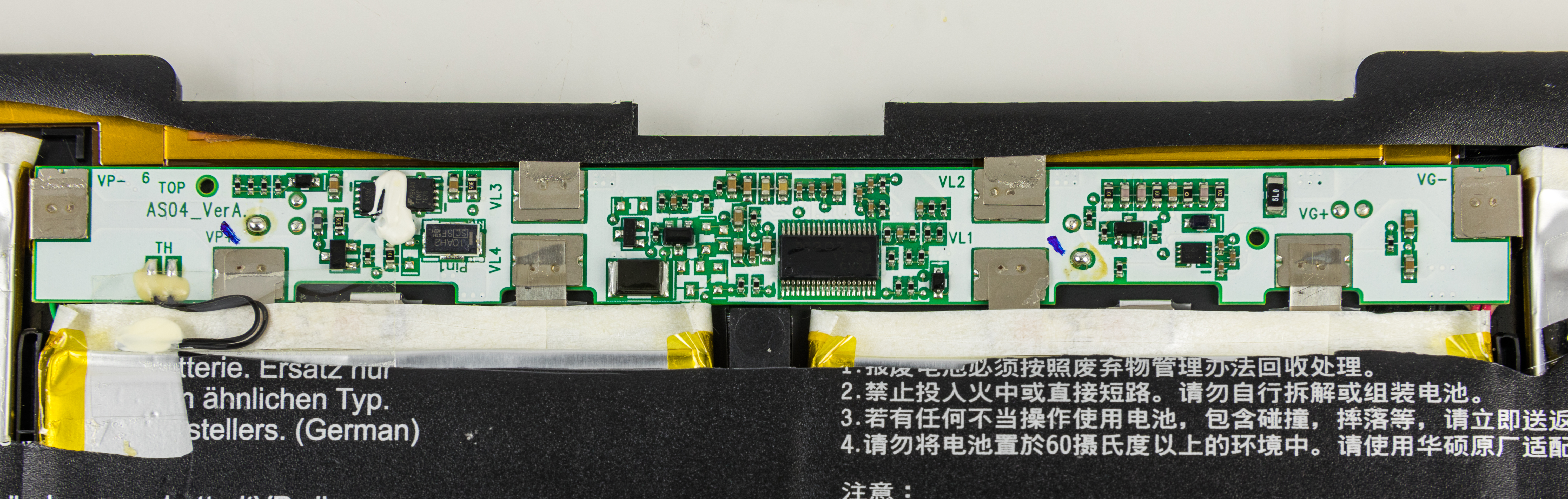
A battery protection PCB is a circuit that detects specified abnormal conditions and acts on the battery’s power path. It is not automatically a charger or a complete battery management system (BMS). To specify one, define the cells and pack topology, the faults it must detect, what happens after each fault, and how the board interacts with the charger and load.
Start with the cell manufacturer's requirements and the actual system. Board labels such as “protection PCB,” “PCM” and “BMS” do not establish which functions are present. For the separate question of cell balancing, see BMS balancing board design.
Protection, charging and management have different jobs
These functions may share a board, but they should be specified separately:
- Protection detects defined abnormal conditions and initiates a protective response, often by controlling external switches in the charge or discharge path. The conditions, response and recovery depend on the design.
- Charging controls energy delivered to the battery according to the selected cells’ charging requirements. Normal charge termination is a charger function; a protective overvoltage cutoff is not a substitute for it.
- Battery management can combine monitoring and protection with functions such as balancing, diagnostics or communications. Those functions are implementation choices, not guarantees implied by the BMS label.
The distinction is visible in component documentation. Texas Instruments’ BQ2970 family, described in datasheet SLUSBU9I, is a single-cell protector used with external FETs. Its exact device suffix and configuration matter to threshold and recovery behavior; the family name does not establish temperature protection for a module.
The BQ24072, described in datasheet SLUS810N, is a single-cell charger with defined charge phases. It is not a universal substitute for pack protection. The BQ76952, described in datasheet SLUSE13B, is a configurable monitor and protector that needs external circuitry; the IC alone is neither a finished BMS nor a CC/CV charger.
An evaluation board can help an engineer study a device, but it is not evidence of a qualified production pack. For example, the BQ29700EVM-610 is an evaluation board, not proof that a particular battery assembly has passed system validation.
Choose the functions before choosing the board
The right level of protection depends on the pack and the equipment around it. Use the following questions to establish the functional boundary:
- What is being protected? Identify the cell chemistry and exact cell model, the series/parallel configuration, and the cell manufacturer’s limits and application requirements.
- Who controls charging? Identify the charger, its interface to the pack and its normal charge-control behavior. State whether the charger is on the protection board or elsewhere.
- What must be interrupted? Identify charge and discharge paths, shared or separate ports, and any connections that must remain available for monitoring or communications during a fault.
- What needs to be measured? Specify the required cell or pack voltages, current direction, temperature sensing locations and any diagnostics. Do not assume that a board measures every cell or every relevant hot spot.
- What happens after a fault? Define whether operation resumes automatically, requires a charger or load condition, needs a command, or requires another intervention. Confirm this for each protection function.
- What management functions are needed? State whether balancing, communications, status reporting or event recording is required. If none is required, say so.
A simple protector may be appropriate for a design with limited functional requirements, while a more configurable monitor/protector may be appropriate where the system needs more visibility or control. Neither choice removes the need to specify and validate the surrounding circuitry and pack.
Fault-to-evidence decision table
For every applicable fault, request the detection condition, threshold and tolerance, delay, sensing location, power-path response and recovery condition. Ask for the exact device suffix, configuration and supporting evidence.
| Fault or behavior | Define for the application | Questions for the board supplier or design owner |
|---|---|---|
| Abnormal voltage | Which cell or pack voltages must be monitored during charge and discharge? Which cell manufacturer requirements apply? | What overvoltage and undervoltage conditions are detected? What are their thresholds, tolerances and delays? Where is voltage sensed? Which path is interrupted, and what releases the protection? |
| Charge overcurrent | Continuous and peak charge current, peak duration, charger behavior and intended charge path. | How and where is charge current sensed? What threshold, tolerance and delay apply? Does the response stop charging only, or affect discharge too? What charger condition permits recovery? |
| Discharge overcurrent | Continuous and peak discharge current, peak duration and the load’s expected behavior. | How and where is discharge current sensed? What threshold, tolerance and delay apply? Which path is interrupted? Does recovery depend on removing the load, waiting, or another condition? |
| Short circuit | The locations at which a short must be addressed and the intended response of the pack and connected system. | How is a short distinguished from another overcurrent condition? What detection threshold, tolerance and delay apply? What interrupts the current, and what are the recovery conditions? What evidence supports the stated behavior? |
| Temperature | Whether temperature protection is required for charging, discharging or both; the cell manufacturer’s requirements; and the locations that need sensing. | Is temperature sensing actually fitted and enabled? Where are the sensors placed? What conditions, thresholds, tolerances and delays apply? Which path is affected, and when is operation allowed to resume? |
| Recovery and charger interaction | Expected behavior after each fault, including what the charger and load will do while the path is interrupted. | Is recovery automatic or conditional for each fault? Does connecting or removing the charger or load change recovery? Can the charger resume normal control without repeatedly driving the protector into cutoff? What is observable to the system? |
A threshold needs its tolerance and delay. A cutoff specification also needs to identify the affected path and recovery behavior. Request the conditions under which the supplier's evidence applies, including the configuration and connections used.
Temperature deserves particular attention: a protector IC or module name does not establish that a temperature sensor is present, where it measures, or whether it controls charging, discharging or both.
Specify the electrical and mechanical interface
A useful requirement describes the pack in operation, not just its nominal label. Include:
- Cells and topology: chemistry, manufacturer and model; number of cells in series and parallel; and any relevant cell manufacturer documents.
- Current profile: continuous and peak charge and discharge currents, peak durations and expected operating conditions. Keep charge and discharge requirements separate.
- Connections: cell taps, pack output, charger connection, load connection, sensor connections and any communication or status interfaces. Identify shared and separate charge/discharge paths.
- Charger: manufacturer and model where selected, its intended operating behavior and how it responds when the battery path is interrupted.
- Environment: operating and storage conditions relevant to the assembly, expected thermal constraints, enclosure and exposure conditions.
- Physical constraints: board outline, available height, mounting, connector and cable interfaces, clearances and how the PCB fits within the pack.
- Functional requirements: required protection, sensing, diagnostics, balancing and communications, including what the host must be able to observe or control.
For parallel cells, document the intended connections and assumptions about current sharing rather than treating the pack’s total current as sufficient design information. For series cells, state which individual cell or group voltages must be available to the protection and management circuitry.
Also identify the source of each requirement. A current profile from the load, charging limits from the cell manufacturer and a connector constraint from the enclosure are different inputs; keeping them traceable makes later changes easier to assess.
What to put in a fabrication or assembly RFQ
A board fabrication or assembly quote is most useful when the supplier can identify exactly what is being built and which questions remain open. Provide revision-controlled files and state whether the request covers the bare board, component sourcing, assembly or a combination.
Include, as applicable:
- The PCB design revision and fabrication outputs, with material, stackup and other board requirements identified by the design owner.
- The assembly revision and relevant bill of materials, including manufacturer part numbers, approved alternatives and any parts supplied by the customer.
- Assembly documentation, component placement information and notes needed to distinguish fitted and unfitted options.
- Electrical, thermal and mechanical constraints that affect the board or assembly, including the interfaces and current profile described above.
- Quantity and the intended build stage, so the request is tied to a specific scope.
- Inspection requirements and the records or other evidence requested with the build.
- Open feasibility questions, including any design features, components or documentation the supplier should review before quoting.
The components and BOM guide and design-for-assembly checklist are useful starting points for preparing the package. Do not leave protection settings or component substitutions implicit: an alternate component or configuration can change the behavior that the design owner needs to verify.
Ask APTPCB to confirm the requested fabrication or assembly scope and feasibility. Do not assume that a board quote includes cell-pack design, safety testing, certification or system qualification.
Plan verification at board and pack level
Agree on evidence before release, and connect it to the requirements in the fault table. At the board or assembly level, the design owner should identify how the delivered revision and fitted components will be checked against the approved files and BOM. Any inspection or documentation requested from the supplier should be explicit in the RFQ and confirmed as part of the agreed scope.
Separately, the responsible engineering team needs a pack and system validation plan using the actual cells, charger, load, enclosure and intended interfaces. That plan should define the applicable conditions, acceptance criteria and records for:
- Protection detection, interruption and recovery for each specified fault.
- Charger and load behavior before, during and after a protective interruption.
- Required sensing, diagnostics, balancing and communications, where implemented.
- Electrical and thermal behavior in the intended assembly and environment.
- Applicable safety and compliance requirements for the finished product and its intended market.
The plan should also identify who owns each activity and which hardware and configuration were evaluated. A fabricated PCB or assembled protection circuit is one part of that evidence; it does not by itself establish finished-pack or system-level safety or compliance.
When the requirements and build package are ready, request a quote or contact APTPCB with the files, quantities, requested evidence and questions about scope.