
Choose a PCB surface finish by starting with the most demanding exposed feature: a fine-pitch solder pad, a wire-bond site, or a connector contact. For ordinary soldered through-hole and larger-pitch parts, HASL may be practical. For flatter solder pads, ENIG is often worth considering. If the design also requires wire bonding, ENEPIG is a candidate—but the actual bonding system must be qualified. Repeatedly mated contacts may instead need selective hard gold.
The finish decision belongs in the drawing and procurement package, not just in a purchase-order dropdown. Assembly alloy, pad geometry, storage, bonding specifications and contact wear requirements can all change the appropriate choice.

What the finish does—and what it does not do
A surface finish covers exposed copper before assembly. Its immediate jobs are to protect that copper and provide a surface suitable for the intended operation, such as soldering. The finish can also affect pad flatness, handling sensitivity and the interfaces formed during assembly.
Solder mask is different. It is the protective coating that covers selected areas of the board, leaving openings for pads, contacts and other features. It does not replace the finish on exposed copper. Mask opening dimensions and alignment can still affect printing, soldering and bonding. For the mask side of the design, see What Is Solder Mask?.
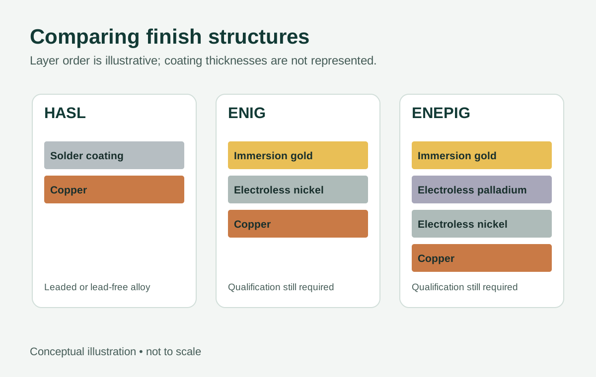
The four finishes compared here have different layer structures:
- HASL: A tin-lead solder coating is applied to exposed copper and leveled with hot air.
- Lead-free HASL: The same general process uses a lead-free solder alloy. The alloy composition should be specified or confirmed.
- ENIG: Electroless nickel is covered by a thin layer of immersion gold.
- ENEPIG: Electroless nickel is followed by electroless palladium and then immersion gold.
The gold in ENIG and ENEPIG is not a thick, wear-rated contact coating. Its role is associated with protecting the underlying finish; its presence alone does not establish suitability for repeated mating or for a particular bonding wire.
Compare the finishes at the exposed feature
| Finish | Soldering and planarity | Storage and handling | Bonding and contacts |
|---|---|---|---|
| Tin-lead HASL | A familiar solderable coating for compatible assemblies. Its leveled solder can be uneven, so assess small pads and coplanarity-sensitive parts. | Protect from contamination and oxidation; agree on packaging, age limits and acceptance criteria. | Do not assume suitability for wire bonding or repeated sliding contacts. Lead content may rule it out for the product or assembly process. |
| Lead-free HASL | Suitable for compatible soldering processes, but alloy and pad topography matter. It can also be less planar than ENIG or ENEPIG. | Storage acceptance depends on the actual coating, package and conditions; do not transfer a shelf-life figure from another supplier or alloy. | Lead-free finish alone does not qualify a bond or contact interface. Confirm the specific alloy and application. |
| ENIG | Generally flatter than HASL and often considered for fine-pitch solder pads. The nickel interface and finish quality remain important to solder-joint reliability. | Protect the surface from damage and contamination. An intact-looking gold surface is not, by itself, a solderability test. | Not automatically suitable for wire bonding. Thin immersion gold should not be treated as a specified wear surface. |
| ENEPIG | Generally planar and usable for soldering when its layer structure and assembly process are compatible. | Bond areas can be sensitive to contamination and handling; agree on protection and the point at which the packaging may be opened. | A candidate for some wire-bonding applications, subject to wire, equipment, pad and process qualification. It is not automatically a substitute for hard gold on a wear contact. |
Planarity is a relative advantage, not a guarantee of assembly yield. A flat finish cannot compensate for an unsuitable footprint, board warp, poor paste release or a component whose coplanarity is out of specification.
Solder alloy, reflow and finish must work together
Tin-lead HASL contains lead; lead-free HASL does not use a tin-lead coating. That distinction matters when setting up solder alloy compatibility and assessing the product’s regulatory or customer requirements.
Do not equate “lead-free finish” with a compliant finished product. Compliance depends on the applicable requirements and on materials beyond the PCB finish. Conversely, a project that permits tin-lead solder should still check whether its components, assembler and intended process support that choice.
For ENIG and ENEPIG, consider the finish as part of a solder-joint system. During soldering, the deposited layers interact with the molten solder and the underlying metals. Finish condition and layer thickness therefore matter as well as the visible appearance. If a design has demanding reliability requirements, agree on applicable finish acceptance criteria and qualification testing rather than specifying only the finish name.
The number of allowable thermal excursions is also project-specific. A board may see fabrication heating, one or more assembly passes, selective soldering and rework. The effect depends on the finish, thermal exposure and assembly requirements; there is no universal reflow count that can safely be attached to a finish name.
Melexis’s Guidelines for SMT soldering, Rev. 1 (2020), is an example of a component manufacturer’s document to review when planning soldering and handling. Its requirements apply to the relevant Melexis devices; they should not be generalized to every component or board. Use each device’s applicable documentation alongside the board and solder-material specifications.
Paste selection is another independent decision. The alloy, flux, stencil and reflow process must be compatible with the parts and board; see Solder Paste Selection.
Wire bonds and contacts need their own specifications
ENIG versus ENEPIG for bonding
ENEPIG adds a palladium layer between nickel and immersion gold. That makes it worth evaluating for certain bonding applications, but “ENEPIG” is not a complete bonding specification.
The RFQ should identify the bond type, wire material and diameter, pad dimensions, finish layer requirements and the bonding equipment or process to be qualified. It should also state the required bond acceptance method—for example, the applicable pull or shear criteria and sampling plan. A supplier can then review whether the requested finish and controls match the application.
Do not substitute ENIG for ENEPIG, or vice versa, solely because both have a gold surface. If a proposed substitution is necessary, route it through the device owner and bonding-process qualification before release.
ENEPIG versus selective hard gold for contacts
Selective hard gold is a different approach, typically using an electroplated gold coating over a suitable underlayer on designated contact areas. It is intended for applications where a more wear-resistant contact surface is required. Its suitability still depends on coating specification, contact design and the mating environment.
For edge fingers or other sliding contacts, specify the mating material, contact force, number of insertions or mating cycles, environment and acceptance criteria. A cycle target without those conditions is incomplete. Also identify the contact area precisely on the drawing; a board can need solderable pads in one region and a different finish in another.
A mixed-finish design needs fabrication review. Confirm the finish boundaries, achievable processing sequence, coating thickness, masking and inspection requirements before relying on it. Do not assume that a hard-gold region can be substituted for an ordinary solder-pad finish without assembly review.
Storage: agree on conditions, not a universal shelf life
A board’s usable storage period is affected by its finish and packaging, but also by the actual storage environment, handling, contamination and the operation to follow. Solderability and bondability are not necessarily interchangeable acceptance decisions.
For procurement, record the fabrication or shipment date, package type, storage conditions and the point at which the package is opened. If a bonding operation has special cleanliness or exposure limits, include those separately from the soldering requirements. Protect contact and bond surfaces from fingerprints, abrasion and unnecessary probing.
If boards are older than the agreed limit, show damaged packaging, or have an uncertain storage history:
- Quarantine the affected lot and preserve the lot and storage records.
- Ask the fabricator and assembler to review the exposure against the agreed criteria.
- Decide on representative testing or disposition appropriate to the intended operation. A solderability result alone does not qualify a wire bond or a wear contact.
- Do not automatically clean, rework or assemble the lot. An unapproved cleaning or rework step can change the surface needed for the process.
The applicable post-assembly cleaning process also deserves review, particularly around sensitive interfaces. See Cleaning After Soldering.
Three decision examples
The following examples are hypothetical. Their dimensions, storage periods and cycle targets are assumptions for explaining decisions, not measured results or APTPCB capabilities.
1. Through-hole controller with a compatible tin-lead process
Hypothetical: A controller uses through-hole connectors and relatively large-pitch surface-mount parts. The product requirements permit lead, and the assembler has an approved tin-lead process.
Tin-lead HASL is a reasonable finish to discuss because the exposed features are primarily soldered and the assembly alloy permits it. Before ordering, the buyer should confirm the smallest pad geometry, the assembler’s tolerance for coating variation and the applicable lead requirements.
If a later revision adds a coplanarity-sensitive fine-pitch device, revisit the finish rather than carrying the original choice forward automatically. If lead is prohibited by the customer or applicable rules, tin-lead HASL is not the right assumption.
2. Fine-pitch assembly with a planned storage period
Hypothetical: A lead-free assembly includes a 0.5 mm-pitch BGA and the buyer expects bare boards to remain in storage for nine months before assembly.
ENIG is a candidate because its flatter surface can help address pad-planarity concerns. Lead-free HASL may still be worth reviewing, but the decision should consider the actual pad geometry and assembler’s process—not pitch alone.
Nine months is a planning assumption, not an ENIG shelf-life claim. The RFQ should state the desired duration and storage conditions and request packaging and acceptance recommendations. If the supplied packaging or agreed storage history cannot support the planned hold, change the logistics or establish a suitable acceptance plan before assembly.
3. Board with wire bonds and a sliding edge contact
Hypothetical: A product calls for 25 µm gold wire bonds to board pads and an edge connector with a target of 100 mating cycles under a defined contact load and environment.
ENEPIG is a candidate for the bond pads; selective hard gold may be appropriate for the edge fingers. Neither choice is qualified by its name. The bonding owner must define and validate the wire, pad, surface and bond-test requirements. The connector owner must define the mating contact, force, environment and wear acceptance.
The fabrication drawing should show both regions and their boundaries. If the proposed mixed-finish sequence cannot be supported or qualified, resolve the design or process change before ordering—not after the boards arrive.
Turn the finish choice into an RFQ
Use the following checklist when requesting an APTPCB quote or discussing an exception. Provide the project requirements; do not assume a finish, test or mixed-finish process is available without confirmation.
| RFQ item | Information to transfer | Question to resolve |
|---|---|---|
| Finish and locations | Finish name, lead restrictions, drawing revision and exposed regions; identify any selective finish boundaries. | Can the requested finish or combination be reviewed for this design? |
| Layer and acceptance requirements | Required layer thickness ranges, applicable finish standard and revision, measurement and acceptance criteria. | How will conformance be documented, and how will out-of-specification material be handled? |
| Solder assembly | Smallest relevant pads, component requirements, solder alloy, assembly sequence and expected rework exposure. | Does the assembler accept the proposed finish and board condition for its process? |
| Wire bonding | Wire material and diameter, pad geometry, bonding process, cleanliness requirements and pull or shear criteria. | What qualification and handling controls are required before production bonding? |
| Contacts | Mating material, geometry, force, cycle target, environment and wear acceptance. | Does the specified selective finish address the actual contact system? |
| Packaging and storage | Planned hold time, storage conditions, packaging and labeling needs, shipment destination and handling restrictions. | What packaging and storage conditions are agreed, and what happens if they are exceeded? |
| Inspection and changes | Required documentation, sampling, lot traceability and approval route for substitutions. | Who approves a finish change, a damaged package or an aged lot? |
Use quote to submit the drawing and finish requirements, or contact to discuss an unresolved bonding, contact or packaging question before release.
The practical choice
For a solder-only board with forgiving geometry, either form of HASL may be worth considering if the alloy meets the assembly and product requirements. ENIG is often a candidate when flatter pads matter. ENEPIG deserves consideration when soldering and a qualified bonding application share a board. Selective hard gold addresses a different need: a specified contact interface subject to mating and wear.
The best finish is the one whose location, layers, handling and acceptance criteria are defined for the actual board. If those details are missing, resolve them with the assembler, bonding or connector owner and fabricator before treating the finish name as an approved specification.