
An oval shape on a PCB drawing can mean a plated terminal opening, an unplated mechanical slot or merely the outline of a copper pad. Those are different manufacturing instructions. Specify the required opening, its finished width and overall length, its position and whether its walls must be plated. Then check the exported manufacturing files rather than relying on the appearance of the footprint in the editor.
A plated slot may connect a flat component terminal to the board. A non-plated slot may provide clearance for a tab, a mechanical adjustment or a deliberate interruption of the board material. The required function determines the copper and wall condition; neither choice can be inferred reliably from shape alone.
The broader file package is covered in fabrication drawing essentials. For ordinary circular plated-hole lands, see annular rings and drill tolerance. Slot fit additionally depends on the elongated geometry, end shape and alignment of the mating part.

Real bare-board photograph by Vishnu Mohanan / Unsplash, used as fabrication context. A specified plated or non-plated slot is not identified in this photograph; the conceptual wall sections below distinguish the two conditions.
When should a slot be plated?
Use a plated slot when the design requires a conductive wall, such as a soldered flat terminal with a copper land connected to the intended net. Define the land and its connectivity along with the opening. A plated wall does not automatically mean the slot should connect to every internal copper layer it passes through.
Use a non-plated opening when the walls must remain nonconductive or the feature serves a mechanical clearance function without a conductive barrel. Review clearances to all relevant copper, not just the visible top layer. An unplated wall can still be close to internal copper or exposed copper on a neighboring edge.
Do not add plating to rescue an ambiguous drawing. A metal locating tab that fits a non-plated opening may not fit after wall plating reduces the available opening. Conversely, fabricating a terminal slot as non-plated can remove the conductive path the design expected.
| Function | Information that resolves the choice | Mistake to prevent |
|---|---|---|
| Soldered blade terminal | Plated wall, land geometry, net and assembly requirements | Treating a rectangular pad outline as proof of a slot |
| Mechanical tab clearance | Finished opening, wall condition and mating-part envelope | Allowing process compensation or plating to consume clearance |
| Adjustment slot | Travel range, fastener envelope and locating datum | Checking width but overlooking end-of-travel interference |
| Deliberate insulation opening | Electrical safety design, final geometry and applicable requirements | Assuming any visible gap automatically establishes compliant creepage |
A slot used for insulation needs a separate electrical safety review. The effect on creepage or clearance depends on the actual geometry, materials, environment and governing requirements. Do not substitute a general machining note for the product's insulation design.
Which dimensions should the drawing define?
Call out the finished opening, including the state after plating and the relevant finishing operations. Distinguish its width from its overall end-to-end length. If a CAD or inspection system uses distance between end centers, label that explicitly; it is not the same length as the complete opening.
A simple capsule-shaped slot has parallel straight sides and semicircular ends. Its end radius is half the width. With an overall length L and width W, the separation of the end centers is L − W. These relationships describe that particular geometry. They do not apply unchanged to a custom cutout, a relief shape or a routed pocket.
A rotating cylindrical cutter cannot produce a perfectly sharp internal corner. If the mating part has square corners, check its actual envelope against the slot's curved ends. Adding length may help a particular fit, but the required amount depends on corner shape and clearance. Do not assume a rectangle fits because its length and width are each smaller than the slot's maximum dimensions.
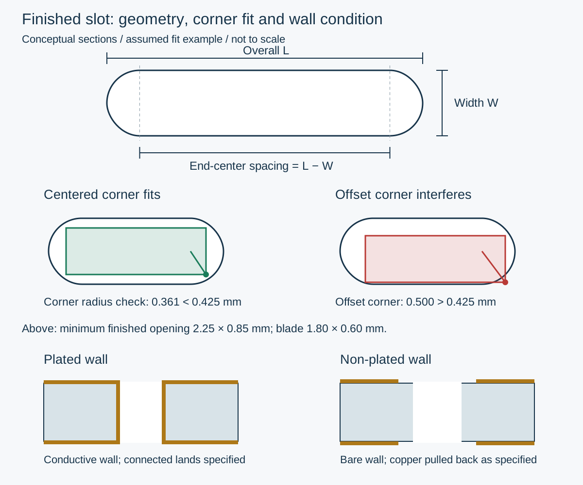
Conceptual geometry, not a fabrication recommendation. The corner positions illustrate the hypothetical fit calculation below; the separate wall sections show the plating distinction without prescribing layer thickness.
A worked fit check for a flat terminal
Assume a hypothetical terminal blade is at most 0.60 mm thick and 1.80 mm wide. The proposed slot is a capsule with finished width 0.90 ± 0.05 mm and overall length 2.30 ± 0.05 mm. The dimensions are invented for this exercise, not taken from a component drawing or a manufacturer's capability table.
For a conservative first check, use the smallest opening: width 0.85 mm and overall length 2.25 mm. With the blade centered, width-direction clearance is (0.85 − 0.60) / 2 = 0.125 mm on each side. That checks the straight sides, but not the blade's corners at the rounded ends.
For the minimum opening, the end radius is 0.425 mm and each end center is (2.25 − 0.85) / 2 = 0.70 mm from the slot center. A blade corner is 0.90 mm along the slot axis and 0.30 mm across it. Its distance from the corresponding end center is sqrt((0.90 − 0.70)² + 0.30²) ≈ 0.361 mm, less than the 0.425 mm radius. The ideal centered rectangle therefore fits this assumed minimum capsule.
That result still does not include position error. If the blade moves 0.10 mm along the slot and 0.10 mm across it, the far corner lies sqrt(0.30² + 0.40²) = 0.50 mm from the end center. That exceeds 0.425 mm. A fit that passes when perfectly centered can fail when the assembly's position budget is included.
Use this as a screening method for a rigid, parallel-sided blade entering a straight capsule. Real terminal corner radii, burrs, angular misalignment, lead-ins and soldering clearance need their own allowance. For several terminals, compare the whole pattern and the component's locating features; independent single-slot checks do not prove that the entire part seats.
Who selects the routing tool and plating allowance?
The design should define the required finished feature. The fabricator proposes how to produce it, including tooling, compensation and process sequence. For plated slots, a manufacturing opening generally needs allowance for the material added to its walls. The required allowance also depends on the controlled process and its tolerances.
Do not enlarge an opening in CAD “for plating” unless the supplier has explicitly requested that data convention and the drawing makes it unambiguous. Otherwise both designer and fabricator may compensate the same feature. Conversely, do not send a tool-size instruction when the intended acceptance requirement is a finished slot dimension.
A supplier may route a slot or create it through an approved sequence of overlapping drilling operations. Confirm whether the proposed process delivers the required wall condition and fit. Process-specific minimum widths and lengths belong to that supplier and service. They are not universal PCB design limits, and a technically possible feature may still require special handling or cost.
How can a slot be represented in KiCad manufacturing data?
KiCad 9.0 documents separate controls for the pad and its hole. A copper pad can have an oval outline while its hole remains circular. For a plated terminal slot, check the through-hole pad's hole shape and its two dimensions as well as the copper land. For a non-plated pad feature, confirm its NPTH/mechanical attribute and required geometry.
The same documentation describes Excellon output for oval holes: normal output uses route commands, with an alternate drill mode available when requested by the manufacturer. Keep this as an explicit supplier compatibility decision. Switching a setting because a viewer looks unusual can create a different interpretation downstream.
After export, view the copper, outline and drill/routing data together. Confirm a common origin, units, orientation and intended slot count. Check that the opening is present in machine-readable data and that its plating class remains identifiable. A text note is valuable for clarification, but should not be the only evidence that a physical feature exists.
For a practical export check, select one known terminal slot and compare its copper land and the drill-map opening at the same coordinates. An oval copper land with only a circular drill symbol is not the intended oval hole. In the drill/routing viewer, verify both rounded endpoints and the finished-opening dimensions specified by the drawing; then check the file's plating class against the slot table. Record that feature's ID in the CAM clarification if the imported shape or class differs.
For an arbitrary internal cutout, agree the accepted profile-data convention with the fabricator. Avoid delivering two conflicting definitions of the same opening in different files. Identify which released file and drawing dimension control if the viewer or CAM import reports a discrepancy.
What should inspection and receiving verify?
Assign IDs to critical slots. For each, record width, overall length, position datum, orientation, plating state and applicable land or copper-clearance requirements. Define the dimensions and conditions that must be measured, rather than requesting a generic “slot inspection.”
A width gauge does not establish overall length or true position. A visual view of a shiny wall does not establish plating thickness or the quality of the entire wall. Choose the evidence needed for the feature's actual electrical and mechanical role, with sampling and acceptance agreed for the order.
If a terminal will not seat, quarantine the affected parts and compare the released component drawing, actual terminal, finished opening and hole pattern before adjusting either part. Filing the board or forcing the terminal can damage copper and conceal the cause. Any repair that changes geometry or a plated wall needs an approved disposition.
Check the assembly drawing for insertion direction and keepouts, and the panelization arrangement for handling and access. A slot that is correct on an individual board may still conflict with a panel rail or assembly fixture.
Send a finished-feature specification for quotation
Include the board files, a dimensioned slot table, the mating component drawing and the identified plating classes. Mark fit-critical slots and distinguish controlled dimensions from reference dimensions. State whether the requested scope includes dimensional reporting, special wall inspection or an assembly trial.
Use the quote page or contact page with the actual data and open questions. Agree the manufacturing interpretation before releasing tooling. The product design owner approves the mechanical fit and insulation design; the fabricator's feasibility review addresses the proposed board construction and agreed deliverables.
Technical reference basis
KiCad 9.0, PCB Editor, pad properties and drill-file generation, establishes the software behavior described here. Component drawings establish the real mating dimensions. The capsule relationships and tolerance exercise are independent geometric examples with declared assumptions, not prescribed production limits.