
A PCB test coupon is a purpose-built test structure made to represent selected features of a circuit board. It gives the manufacturer or quality team a place to measure or examine those features without necessarily cutting into a usable product board. An impedance coupon, a plated-hole coupon and a solderability specimen answer different questions; a pass on one does not establish that the others have passed.
The useful starting point is not “Which coupon comes with the board?” but “What decision must the result support?” Identify the feature, the manufacturing conditions the coupon should represent, the test and acceptance criteria, and the production units to which the result will be linked. Agree those details with the fabricator before the panel and test plan are released.
For a closer look at destructive examination, see microsection coupon strategy. For the interpretation of a measured TDR waveform, see how to read an impedance coupon TDR report. The focus here is how to choose and request evidence across several different verification questions.
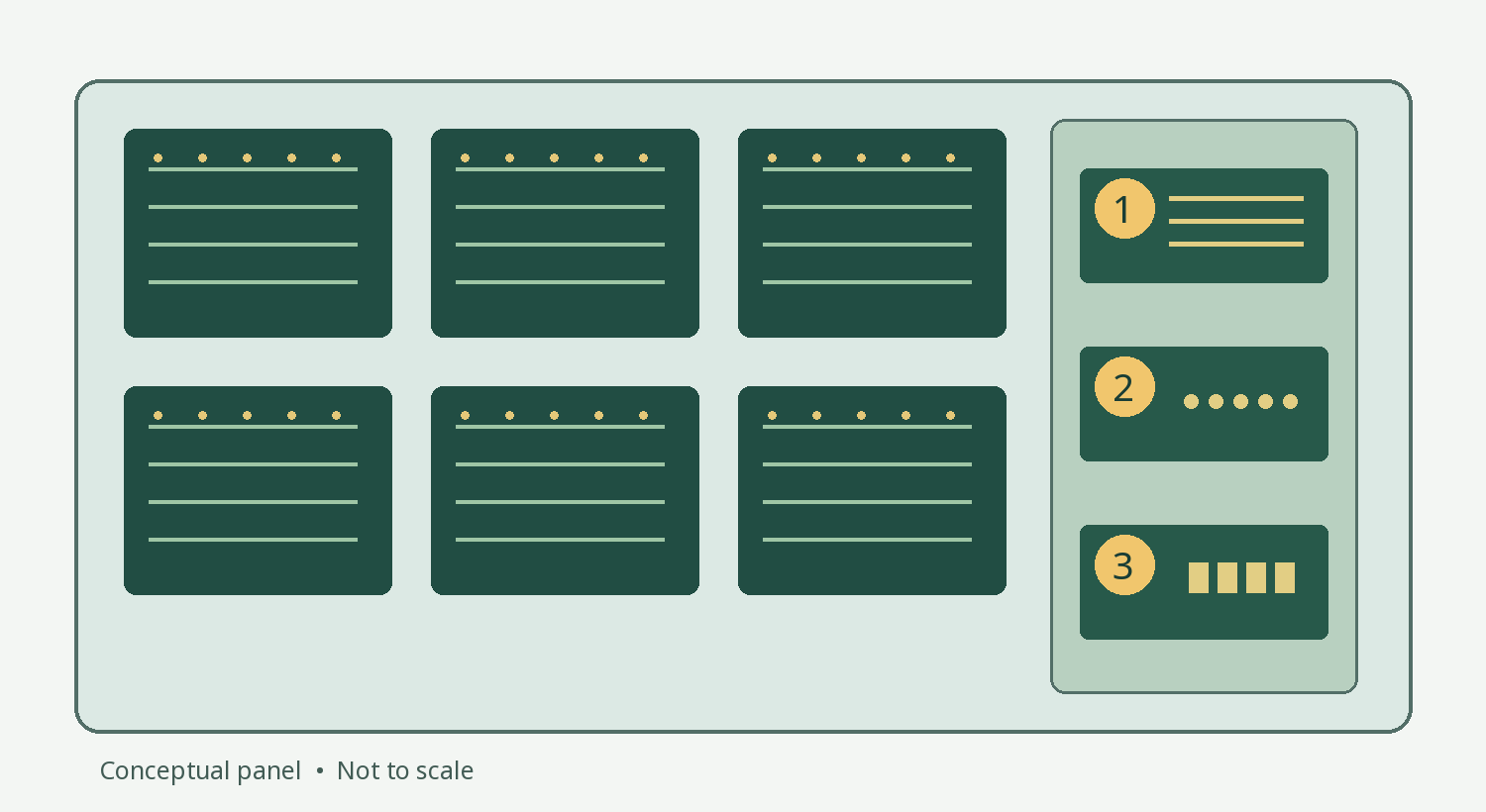
The drawing is a conceptual panel, not a manufacturing layout or a prescription for coupon count. The numbered structures represent 1 an impedance line, 2 plated-hole structures for sectioning, and 3 a separate surface-finish specimen. Actual designs, placement and testing depend on the agreed plan.
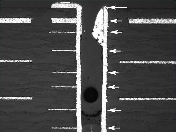
Coupon through-hole microsection from a 2009 NASA/GSFC inspection example. The original arrows identify missing internal and external annular rings. This is a source defect example, not an APTPCB specimen or a universal acceptance limit. Source: Charles E. Powers, NASA Goddard Space Flight Center. Image credit and source record.
What does a test coupon represent?
A coupon contains features selected for a particular measurement: a controlled transmission line, plated holes, surface lands or another pattern. It can be fabricated alongside production boards on the panel or in another agreed arrangement. The relevant connection to the product is the construction and process history, not merely that the specimen has the word “coupon” printed on it.
For a plated-hole examination, representation may depend on the layer construction, drilled feature, hole depth, plating sequence and connections being investigated. For impedance, it includes the controlled layer, dielectric and reference arrangement, trace geometry and measurement access. For a surface-finish question, the exposed features, finish and subsequent handling matter. Which details must match depends on the test and the product risk.
A coupon is not a miniature functional copy of the whole board. It can deliberately simplify a structure to make a measurement repeatable. That simplification is useful only if the team understands what has been left out. A straight line used for impedance measurement, for instance, does not reproduce every connector launch or layer transition in the product.
Is a coupon the same as a bare-board electrical test?
No. Bare-board electrical testing checks the product board's accessible electrical connections against an agreed netlist and test coverage. A coupon measures or subjects a separate test structure to an agreed examination. A cross-section may reveal the internal construction at a selected location, while an electrical test can reveal an open or short within its own coverage. Neither result replaces the other automatically.
A test vehicle is another purpose-designed board or structure used to evaluate a design or process. It may be more elaborate than a coupon and may be built separately. Whether it represents a specific production lot depends on its construction and processing history, not its name. Ask what the specimen actually represents before using its report for release.
Read the identity before the number
A report should connect a measured value to a named structure, board revision and panel or lot. The example below shows why those fields matter: its impedance value falls inside the assumed interval, but its reported revision differs from the released revision.
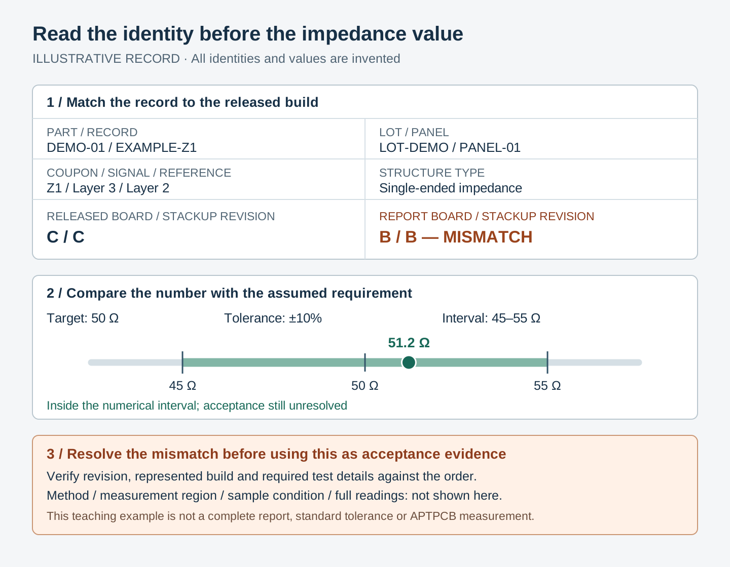
Illustrative record only; all identities and values are invented. The assumed 50 Ω ±10% requirement gives 45–55 Ω, so 51.2 Ω is numerically inside the interval. The revision mismatch still needs resolution. These values are not a recommended target, a standard tolerance or an APTPCB measurement. Method, measurement region, sample condition and all required readings must also match the order; this simplified example is not a complete test report.
Match the question to the specimen
| The question before release | Candidate specimen and evidence | What remains outside that result |
|---|---|---|
| Was a selected controlled structure manufactured close to its target? | A representative transmission-line coupon, measured by the agreed impedance method and reported with its structure and layer identity. | Complete channel behavior, connectors and transitions not represented by the coupon. |
| What is visible inside a selected plated hole or layer interface? | A representative structural specimen, prepared as a microsection and documented with the agreed observations and criteria. | Unsampled holes, other section planes and future field life. |
| How does a specified interconnect structure respond to an agreed thermal stress? | A relevant hole or via chain and an agreed stress and measurement procedure. | Every product interconnect and every condition the product will encounter. |
| Can the selected finish and features wet under the specified test? | A solderability specimen with agreed feature, finish, condition and method. | Assembly results for every component, paste, profile and storage history. |
| Is another property such as mask adhesion or foil adhesion in scope? | A specimen designed for that property and a separately agreed method and criterion. | Other properties that were not measured. |
This is a planning aid, not a universal inspection package. The applicable contract and specifications determine which tests are required. A purchase order can call for more than one specimen, and a particular structure may support more than one examination if the methods and sequence allow it. Confirm the sequence: a destructive section cannot later be used as an intact electrical specimen.
IPC's published IPC-2221B Appendix A, version 3.0, August 2019 illustrates the distinction: its examples include different structures for thermal-stress evaluation of plated holes, through-hole solderability, surface-mount land solderability and controlled impedance. The presence of a letter in that historical document does not, by itself, establish the current governing revision, required frequency or acceptance limit for an order. Identify the documents and revisions actually invoked in the fabrication and purchase requirements.
How closely must the coupon match the board?
Match the features and processes that affect the result being requested. For a controlled line, compare the approved stackup, signal layer, reference configuration, copper and dielectric assumptions, trace width and, for a differential pair, spacing. Agree which product structures each line represents. A different reference arrangement or a later stackup change can weaken the intended correlation even when the test itself is carried out correctly.
For a structural specimen, list the holes or vias that matter. A through-hole sample does not automatically represent a blind via or a complex sequence of buried and stacked interconnects. Where a critical feature uses a particular layer span or construction, ask whether the specimen reproduces that feature and its relevant fabrication sequence. A section through one location remains a local view; preparation and the plane of section affect what is visible.
The panel layout also deserves review. A coupon placed in a rail may be convenient to remove and test, but location alone does not establish that it experiences every local condition of every board. Ask the fabricator how placement, panel pattern, process and sampling relate to the specific question. There is no useful universal promise that a fixed number at fixed positions covers every design.
If a separate test vehicle is used, document any differences in material, layout, processing, location or time. It may be useful for process development or qualification while being a weaker basis for accepting a particular production lot. The engineering and quality teams should decide whether that distinction is acceptable for the intended use.
A practical example: one panel, several unanswered questions
Suppose a design team orders a multilayer board with controlled differential lines, plated through-holes and a separate blind-via structure. The buyer asks for “a coupon report” but does not specify the test. The supplier proposes an impedance coupon for the controlled lines. That report could address the measured line structure, provided it correlates with the released stackup, but it would not answer whether the blind-via construction was examined.
Before release, the team separates the questions:
- Identify the impedance structures and layers, targets and tolerances, and agree the measurement and report scope.
- Identify the through-hole and blind-via features for which structural evidence is required. Review whether the proposed sectioning specimen represents each relevant feature and manufacturing sequence.
- Define how the selected specimen and report relate to the panel, lot or other production unit, and who decides whether the result meets the purchase requirements.
- Decide what further board-level testing or product validation is required outside the coupon plan.
If the proposed structural specimen includes only through-holes, the team has found a coverage gap, not evidence that the blind vias have failed. The response may be a revised specimen or another agreed verification approach. This is a hypothetical planning example; it is not a customer result or a standard sampling recipe.
What should the drawing and purchase order say?
The designer or buyer defines the features to verify and the acceptance requirements. The fabricator may propose a coupon once the stackup and panel are known, or the customer may supply one. The order should identify who approves the final design, who tests it and which records are included.
Include the released board and drawing revisions, stackup and fabrication files, then link each critical structure to the evidence needed to assess it:
- Purpose and feature: What property is being assessed? Which layers, holes, trace structures or finish features must the specimen represent?
- Method and acceptance: Which applicable specification, revision, method, sample condition and project limit govern? Who approves an alternative?
- Sampling and identity: What production unit does each result represent, where will the specimen be located, and how will its identity be linked to the panel or lot?
- Sequence and handling: Is the sample tested as manufactured or after an agreed stress? Will it be consumed, retained, shipped or documented in another form?
- Deliverables and timing: Is a report required before release, which values or images must it contain, and who receives it? Confirm availability and price for the order rather than assuming inclusion.
- Changes and exceptions: Who reviews changed material, stackup, via sequence or coupon layout? Who decides whether the change needs revised evidence, and how are missing samples or out-of-limit results resolved and recorded?
Where a controlled-impedance result is required, also identify the target and tolerance for each specified structure and ask how the measured region is selected. Keysight's published TDR example defines measurement conditions and a measurement zone for a particular instrument; the applicable setup for an order must be agreed rather than inferred from a generic screenshot. An impedance value and a signal-loss result are different measurements: an impedance report alone is not a loss report.
The PCB stackup design article helps organize the layer information, while PCB traceability and lot control discusses connecting manufacturing records. When requesting a quote or using the contact page, send the coupon and reporting requirements with the fabrication package so that feasibility, scope and responsibility can be reviewed for the specific build.
How should a report be reviewed?
Start by checking identity: part and revision, the represented production unit, specimen or structure identifier, and the applicable test and acceptance requirements. Then compare the actual result with the agreed limit, including the units and sample condition. A “pass” without a clearly identified requirement and specimen is difficult to use as release evidence. A result without an agreed limit may still be informative, but it does not independently settle acceptance.
For an impedance report, review the structure, layer and measurement region before treating the value as evidence for the corresponding product traces. For a microsection report, identify the feature, specimen condition, observation plane, measured location and any images or scale needed to understand the result. Do not assume that a single view proves the state of the entire hole circumference or every similar via on the panel.
If the result is outside the agreed criterion, preserve the report and specimen where possible, identify the affected production unit, and follow the documented nonconformance process. The appropriate next step may involve measurement review, additional examination or a formal disposition by authorized parties. A retest, by itself, should not silently erase the original result. If the sample is missing or its identity is unclear, agree on a disposition rather than treating missing evidence as a pass.
When an in-range value is not enough
For the example record above, first reconcile the report's revision B with the released board and stackup revision C. Then match the intended layer and reference plane, tested structure and represented panel or lot. Verify the specified method, measurement region, required readings and decision rule for measurement uncertainty or rounding. A number inside the interval cannot resolve the wrong revision or missing results. Obtain a corrected record or document a disposition through the order's agreed process.
If the fabrication drawing, purchase order and quality agreement appear to conflict about sampling, acceptance or report delivery, pause and request a controlled clarification. Do not invent a universal priority among those documents: the contract and authorized parties determine which requirement governs. Keep the clarification with the released revision and test records.
Coupon evidence answers the question assigned to the tested structure. Keep it alongside bare-board electrical tests, assembly inspection, functional tests and product qualification, each with its own coverage and acceptance requirements.
References
- IPC, IPC-2221B Appendix A, version 3.0, August 2019: example coupon designs and stated purposes. Use the revision and performance requirements invoked by the order.
- Keysight, TDR – PCB Impedance Measurement Example: measurement conditions and a defined measurement zone for a particular instrument workflow.
- IPC, IPC-TM-650 2.5.5.12A, Test Methods to Determine the Amount of Signal Loss on Printed Boards: specified signal-loss methods; not a universal substitute for the project's impedance test.