
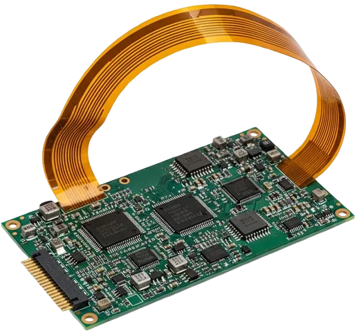
Dynamic rigid-flex circuit reliability in continuous-motion equipment—such as surgical robotics, radar gimbals, avionics linkages, and foldable displays—is governed by conductor strain dynamics rather than simple geometric thickness rules. While static "flex-to-install" assemblies tolerate substantial plastic deformation without electrical interruption, dynamic cycling demands strict adherence to IPC-2223 Class 3 design criteria, maintaining copper conductor strain below the elastic fatigue threshold ($\epsilon \le 0.3%$).
The primary failure mode in high-cycle rigid-flex applications is low-cycle mechanical fatigue of copper conductors, compounded by stress concentrations at the rigid-to-flex transition interface. Achieving multi-million cycle operational life requires aligning conductors with the composite neutral bend axis, enforcing adhesiveless polyimide laminates, and controlling the mechanical impedance step where flexible arms exit rigid board sections.
| Motion Mode | Target Cycle Count | Recommended Stackup Architecture | Min Bend Radius ($R$) | Max Conductor Strain ($\epsilon$) | Mandatory Copper Foil Grade |
|---|---|---|---|---|---|
| Static / Flex-to-Install | $1 - 20$ install cycles | 1- to 2-Layer Symmetrical Core | $\ge 6\times - 10\times T_{\text{flex}}$ | $\le 1.2%$ | IPC-4562 Grade 1 (ED) or Grade 7 (RA) |
| Static Multilayer | $1 - 20$ install cycles | 3- to 6-Layer Bonded Flex | $\ge 20\times - 25\times T_{\text{flex}}$ | $\le 0.8%$ | IPC-4562 Grade 7 (RA) |
| Dynamic Continuous Motion | $> 1,000,000$ cycles | 1-Layer Centered on Neutral Axis | $\ge 40\times T_{\text{flex}}$ (or $100\times t_{\text{cu}}$) | $\le 0.30%$ | IPC-4562 Grade 7 or 8 (High Ductility RA) |
| Dynamic Continuous Motion | $> 1,000,000$ cycles | 2-Layer Staggered Conductors | $\ge 60\times T_{\text{flex}}$ (or $150\times t_{\text{cu}}$) | $\le 0.25%$ | IPC-4562 Grade 7 or 8 (RA) |
| Ultra-High Cycle Dynamic | $> 5,000,000$ cycles | Decoupled Bookbinder (Loose-Leaf) | $\ge 20\times T_{\text{flex}}$ per leaf | $\le 0.15%$ | IPC-4562 Grade 8 (RA Cold-Rolled) |
The Mechanical Physics of Rigid-Flex Bending: Elastic vs. Plastic Strain
When a flexible circuit bends through an angle $\theta$ around a mandrel radius $R$, the outer surface experiences tensile elongation, while the inner surface experiences compressive shortening. Between these opposing stress states lies the neutral axis, where mechanical strain is zero.
                  ======================================  <- Outer Coverlay (Tensile Strain +ε)
                  --------------------------------------  <- Upper Copper Foil (Tension)
                  --------------------------------------  <- Polyimide Core (Neutral Axis: ε = 0)
                  --------------------------------------  <- Lower Copper Foil (Compression)
                  ======================================  <- Inner Coverlay (Compressive Strain -ε)
                                      ▲
                               Bend Radius (R)
                                      ▼
In static applications (such as bending a flex tail inside an avionics housing during final assembly), copper foil can endure moderate plastic deformation ($\epsilon \approx 1.0% - 2.0%$) without electrical discontinuity. However, in continuous dynamic flexing:
- Low-Cycle Fatigue Regime ($\epsilon > 0.5%$): Copper yields plastically on every cycle, accumulating slip dislocations that cause trace necking and micro-fractures within $1,000$ to $50,000$ cycles.
- High-Cycle Fatigue Regime ($\epsilon \le 0.3%$): Copper strain stays within the elastic-plastic transition zone. When designed with high-ductility Rolled Annealed foil, the conductor survives $>1,000,000$ cycles.
- Infinite Life Regime ($\epsilon \le 0.1%$): Strain remains purely within the elastic limit; mechanical fatigue life exceeds $10,000,000$ cycles.
For mission-critical designs produced to IPC-6013 Class 3 rigid-flex capabilities, conductors must be engineered so that calculated operational strain never exceeds $0.30%$.
IPC-2223 Bend Radius Multipliers & Conductor Strain Limits Matrix
The following matrix compares mechanical sizing ratios, maximum allowable copper strain, and standard stackup architectures across static, semi-dynamic, and continuous dynamic operating environments.
| Application Category | Cycling Requirement | Recommended Stackup Architecture | Min Bend Radius Ratio ($R/T_{\text{flex}}$) | Max Conductor Strain ($\epsilon_{\text{allowable}}$) | Permissible Copper Foil Grade | S-N Fatigue Life Expectancy |
|---|---|---|---|---|---|---|
| Static / Flex-to-Install | $1 - 20$ install cycles | 1-Layer Single-Sided Flex | $\mathbf{6\times}$ | $\le 1.50%$ | IPC-4562 Grade 1 (ED) or Grade 7 (RA) | N/A (Static retention) |
| Static / Flex-to-Install | $1 - 20$ install cycles | 2-Layer Bonded Double-Sided | $\mathbf{10\times}$ | $\le 1.20%$ | IPC-4562 Grade 1 (ED) or Grade 7 (RA) | N/A (Static retention) |
| Static / Flex-to-Install | $1 - 20$ install cycles | 3–6 Layer Multilayer Flex | $\mathbf{20\times - 25\times}$ | $\le 0.80%$ | IPC-4562 Grade 7 (RA) Recommended | N/A (Static retention) |
| Semi-Dynamic / Service | $< 10,000$ maintenance cycles | 1-Layer Flex (Centered Axis) | $\mathbf{20\times}$ | $\le 0.50%$ | IPC-4562 Grade 7/8 (RA Foil only) | $10^4 - 5 \times 10^4$ cycles |
| Semi-Dynamic / Service | $< 10,000$ maintenance cycles | 2-Layer Bonded Flex | $\mathbf{30\times}$ | $\le 0.40%$ | IPC-4562 Grade 7/8 (RA Foil only) | $10^4 - 5 \times 10^4$ cycles |
| Dynamic Continuous Motion | $> 1,000,000$ continuous cycles | 1-Layer Flex (Neutral Axis) | $\mathbf{40\times}$ (or $100\times t_{\text{cu}}$) | $\mathbf{\le 0.30%}$ | IPC-4562 Grade 7/8 (RA Foil Mandatory) | $> 10^6$ cycles (Passed IPC-TM-650) |
| Dynamic Continuous Motion | $> 1,000,000$ continuous cycles | 2-Layer Bonded (Staggered) | $\mathbf{60\times}$ (or $150\times t_{\text{cu}}$) | $\mathbf{\le 0.25%}$ | IPC-4562 Grade 7/8 (RA Foil Mandatory) | $> 10^6$ cycles |
| Dynamic Continuous Motion | $> 5,000,000$ robotic cycles | Decoupled Bookbinder Flex | $\mathbf{20\times}$ per individual blade | $\mathbf{\le 0.15%}$ | IPC-4562 Grade 8 (High Ductility RA) | $> 10^7$ cycles (Infinite life) |
[!WARNING] Never specify bonded multilayer flex ($\ge 3$ conductive layers laminated together) for continuous dynamic motion. The shear stress between bonded dielectric layers prevents independent movement, multiplying outer-layer copper strain and causing conductor fracture within fewer than 50,000 cycles. For multilayer interconnects, use decoupled loose-leaf blades.
Mathematical Neutral Bend Axis & Conductor Strain Sizing
In symmetrical single-sided flexible circuits, the neutral axis falls directly in the center of the polyimide core. In asymmetrical rigid-flex stackups (such as dynamic flex layers carrying shielding films or varying coverlay thicknesses), the neutral axis shifts toward the thicker, stiffer material.
1. Neutral Axis Calculation Formula
The position of the neutral bend axis $y_0$ (measured from the inner bend surface) is calculated using composite beam theory:
$$y_0 = \frac{\sum_{i=1}^{n} E_i \cdot t_i \cdot y_i}{\sum_{i=1}^{n} E_i \cdot t_i}$$
Where:
- $E_i$ = Tensile modulus of elasticity of layer $i$ (for Polyimide: $\approx 3.5\text{ GPa}$; for Copper: $\approx 110\text{ GPa}$; for Coverlay Adhesive: $\approx 1.2\text{ GPa}$).
- $t_i$ = Thickness of layer $i$ ($\mu\text{m}$ or $\text{mils}$).
- $y_i$ = Distance from the bottom datum to the centroid of layer $i$.
2. Conductor Mechanical Strain Formula
Once $y_0$ is determined, the mechanical strain $\epsilon$ experienced by any copper conductor layer located at distance $y_{\text{cu}}$ from the datum is:
$$\epsilon = \frac{|y_{\text{cu}} - y_0|}{R + y_0} \times 100% \approx \frac{d}{R} \times 100%$$
Where:
- $d = |y_{\text{cu}} - y_0|$ is the physical offset distance between the copper layer center and the neutral axis.
- $R$ is the inside bend radius.
3. Engineering Worked Example: 1-Layer Dynamic Flex vs. 2-Layer Bonded Flex
Consider a design requiring an inside bend radius $R = 4.0\text{ mm}$ ($157\text{ mil}$):
Case A: Symmetrical 1-Layer Dynamic Stackup (Total Flex Thickness T = 75 µm)
--------------------------------------------------------------------------------
- Top Coverlay: 25 µm Polyimide + 15 µm Adhesive (Centroid y = 62.5 µm)
- Center Conductor: 18 µm (0.5 oz) RA Copper Foil (Centroid y = 42.5 µm)
- Bottom Base Core: 25 µm Polyimide + 15 µm Adhesive (Centroid y = 17.5 µm)
- Calculated Neutral Axis: y0 = 37.5 µm
- Copper Offset d = |42.5 µm - 37.5 µm| = 5 µm
- Calculated Strain: ε = (5 µm / 4000 µm) * 100% = 0.125%  (<= 0.30% -> SAFE for >10^6 cycles)

Case B: Asymmetrical 2-Layer Bonded Stackup (Total Flex Thickness T = 160 µm)
--------------------------------------------------------------------------------
- Top Conductor Layer 1: 18 µm RA Copper at y = 135 µm
- Base Dielectric Core: 50 µm Adhesiveless Polyimide at y = 80 µm
- Bottom Conductor Layer 2: 18 µm RA Copper at y = 25 µm
- Calculated Neutral Axis: y0 = 80 µm
- Outer Copper Offset d = |135 µm - 80 µm| = 55 µm
- Calculated Strain: ε = (55 µm / 4000 µm) * 100% = 1.375%  (>> 0.30% -> CRITICAL FAILURE in <15,000 cycles)
In Case B, the 2-layer bonded board generates $1.375%$ strain at $R = 4.0\text{ mm}$, exceeding the copper elastic limit by more than $400%$. To achieve reliable dynamic life, the designer must either increase the inside bend radius to $R \ge 18.5\text{ mm}$ or decouple the layers into two unbonded 1-layer flex arms.
Rolled Annealed (RA) vs. Electro-Deposited (ED) Copper Fatigue
Specifying standard copper on a rigid-flex fabrication drawing without declaring the metallurgical process is the single most common cause of early field returns in flexing applications.
      Electro-Deposited (ED) Copper Foil              Rolled Annealed (RA) Copper Foil
   [Vertical Columnar Microstructure]               [Horizontal Elongated Grain Structure]
   ┌─┬─┬─┬─┬─┬─┬─┬─┬─┬─┬─┬─┬─┬─┬─┐                  ┌─────────────────────────────────────┐
   │ │ │ │ │ │ │ │ │ │ │ │ │ │ │ │                  ├─────────────────────────────────────┤
   │ │ │ │ │ │ │ │ │ │ │ │ │ │ │ │                  ├─────────────────────────────────────┤
   └─┴─┴─┴─┴─┴─┴─┴─┴─┴─┴─┴─┴─┴─┴─┘                  └─────────────────────────────────────┘
    Vertical grain boundaries act as                 Horizontally aligned grains allow
    micro-crack initiation channels                  dislocation glide; crack paths are
    under cyclic bending tension.                    deflected along the plane.
Metallurgical Comparison Under IPC-4562
| Parameter | Electro-Deposited (ED) Copper (IPC-4562/1) | Rolled Annealed (RA) Copper (IPC-4562/7 or /8) | Dynamic Reliability Impact |
|---|---|---|---|
| Manufacturing Method | Electroplating onto rotating titanium drum | High-pressure mechanical cold rolling & furnace anneal | RA yields a dense, mirror-smooth planar structure |
| Grain Morphology | Vertical columnar crystals perpendicular to foil surface | Elongated, flattened lamellar grains parallel to surface | RA grains slide past each other without boundary splitting |
| Tensile Elongation ($%$ at break) | $5% - 12%$ | $25% - 45%$ | RA provides $>3\times$ higher ductility before necking |
| Fatigue Ductility Exponent ($c$) | $-0.60$ | $-0.40$ (Higher resistance to cyclic strain) | RA survives $50\times - 100\times$ more cycles at identical strain |
| Minimum Trace Roughness ($R_z$) | $3.5\ \mu\text{m} - 7.0\ \mu\text{m}$ (Standard Profile) | $\le 1.0\ \mu\text{m} - 1.5\ \mu\text{m}$ (Very Low Profile) | Lower roughness eliminates notch stress risers |
| Primary Failure Mechanism | Intergranular fracture along columnar boundaries | Micro-void coalescence after severe plastic deformation | ED cracks propagate through full foil thickness rapidly |
The Grain Direction DFM Mandate
When copper is rolled at the mill, its grains elongate in the direction of the roll (Machine Direction).
- Mandatory Rule: Flexible circuit conductors subject to dynamic bending must be laid out so that the grain direction runs parallel to the length of the flex arm (perpendicular to the axis of bend).
- DFM Callout on Fabrication Prints: The master panel drawing must include an explicit note:
"All dynamic flex layers must utilize IPC-4562 Grade 7 or 8 Rolled Annealed copper foil with grain direction oriented perpendicular to the bend axis."
Fabricating dynamic flex panels with grain direction parallel to the bend axis reduces cycle life by up to $70%$.
Rigid-to-Flex Transition Zone DFM Clearances & Keepouts
The transition zone—where the flexible circuit transitions into the rigid multilayer FR-4 stackup—is the most mechanically complex region of a rigid-flex board. In this interface, structural stiffness changes by nearly an order of magnitude over a span of less than $1\text{ mm}$.
                 ===================================================  <- Top Rigid Outer Layer
                 [ FR-4 / Prepreg ] [ Solder Mask ]
                 ===================================================  <- Inner Rigid Layer
                 [ Low-Flow Prepreg ] <--- Cutback 0.5 mm
        ---------------------------------------------               <- Coverlay Extension (0.5-1.0 mm)
   ==== [ Flexible Polyimide Core + RA Copper Foil ] =================== <- Exposed Flex Arm
        ---------------------------------------------               <- Coverlay Extension (0.5-1.0 mm)
                 [ Low-Flow Prepreg ] <--- Cutback 0.5 mm
                 ===================================================  <- Inner Rigid Layer
                 [ FR-4 / Prepreg ] [ Solder Mask ]
                 ===================================================  <- Bottom Rigid Outer Layer
                       |             |                |
                     Rigid       Transition        Exposed
                    Section         Zone          Flex Arm
                       |<-  2.5 mm ->|
                       | Via Keepout |
1. No-Flow / Low-Flow Prepreg Selection
Standard FR-4 prepreg has a resin flow rate of $15% - 30%$. During lamination under heat and vacuum, standard resin spills across the transition interface, forming an irregular, razor-sharp edge ("resin flash" or "resin bead") that cuts into the outer flex coverlay during dynamic bending.
- Specification: The bonding prepreg adjacent to the flex core must be Low-Flow (No-Flow) Prepreg meeting IPC-4101 specifications with resin flow certified between $2.0%$ and $6.0%$ (e.g., Ventec VT-47 No-Flow, Isola 370HR Low-Flow, or Arlon 49N).
- Prepreg Cutback: The prepreg sheet must be cut back by $0.50\text{ mm}$ ($20\text{ mil}$) from the rigid interface profile line to accommodate controlled resin squeeze-out without encroaching into the active bend zone.
2. Coverlay Embedment Depth
Flexible coverlay (polyimide film with thermal adhesive) protects the flex copper traces. In the rigid section, standard coverlay adhesive (acrylic or modified epoxy) has a high coefficient of thermal expansion ($CTE_z > 200\text{ ppm/}^\circ\text{C}$).
- Embedment Depth: The coverlay must extend into the rigid laminate by $0.50\text{ mm}$ to $1.0\text{ mm}$ ($20\text{ mil} - 40\text{ mil}$). This provides an anchored, moisture-impermeable transition seal.
- PTH Keepout Boundary: Coverlay must never extend into the plated through-hole (PTH) field of the rigid board. Plating through coverlay adhesive layers leads to barrel cracking during lead-free reflow ($260^\circ\text{C}$) due to extreme Z-axis expansion. Maintain at least $1.25\text{ mm} - 1.50\text{ mm}$ clearance between the coverlay termination edge and any drilled hole.
3. Plated Via & SMT Pad Keepout
Mechanical bending creates an elliptical shear zone radiating outward from the rigid boundary.
- Via Keepout: All plated through-holes, microvias, and buried vias in the rigid section must maintain a minimum keepout distance of $2.50\text{ mm}$ ($100\text{ mil}$) from the rigid-to-flex transition line. For high-reliability Class 3 designs subject to high shock and vibration, expand this keepout to $3.0\text{ mm}$ ($120\text{ mil}$).
- SMT Pad Keepout: No surface-mount component pads or test points may be placed within $3.0\text{ mm}$ of the transition interface.
4. Strain-Relief Bead Fillet (Epoxy / Silicone)
Under IPC-2223 Section 5.2.8, an elastomeric strain-relief fillet should be applied along the physical step-edge where the flex arm exits the rigid board.
- Materials: RTV silicone (e.g., Dow Corning 732 / 3145) or flexible polyurethane epoxy (e.g., Master Bond EP21LV).
- Function: The fillet redistributes the bending pivot line away from the microscopic resin squeeze-out knife-edge into a smooth, radiused curvature, eliminating local stress concentrations by up to $65%$.
Adhesiveless Polyimide (AP) vs. Adhesive-Based Substrates
Modern high-reliability rigid-flex manufacturing has transitioned decisively from adhesive-based flexible laminates (IPC-4204/1) to adhesiveless polyimide laminates (IPC-4204/11).
| Engineering Parameter | Adhesive-Based Substrate (IPC-4204/1, e.g., Pyralux LF) | Adhesiveless Substrate (IPC-4204/11, e.g., Pyralux AP / Felios) | Reliability Impact on Rigid-Flex Class 3 |
|---|---|---|---|
| Bonding Construction | Polyimide film bonded to copper foil via $15 - 25\ \mu\text{m}$ acrylic adhesive | Direct cast polyimide onto RA copper foil (zero adhesive layer) | Eliminates $30 - 50\ \mu\text{m}$ of total flex thickness, reducing bend stiffness |
| Glass Transition Temp ($Tg$) | Acrylic Adhesive $Tg \approx 40^\circ\text{C} - 60^\circ\text{C}$ | Polyimide $Tg \ge 220^\circ\text{C} - 280^\circ\text{C}$ | Adhesiveless maintains mechanical modulus at reflow temperatures ($260^\circ\text{C}$) |
| Z-Axis CTE ($50^\circ\text{C} - 250^\circ\text{C}$) | $200 - 350\text{ ppm/}^\circ\text{C}$ (Extreme expansion) | $40 - 55\text{ ppm/}^\circ\text{C}$ (Closely matched to copper) | Prevents through-hole barrel stress and inner-layer foil tear-out |
| Moisture Absorption | $2.5% - 4.0%$ | $0.8% - 1.3%$ | Eliminates blistering and delamination during automated soldering |
| Drilling Smear Tendency | Severe acrylic resin smear requiring plasma desmear | Minimal smear; standard permanganate or gentle plasma | Guarantees clean copper-to-copper interconnection on inner flex vias |
| Continuous Operating Temp | Limited to $105^\circ\text{C}$ (UL 796F rating) | Rated to $150^\circ\text{C} - 170^\circ\text{C}$ continuous | Mandatory for aerospace engine bays, automotive downhole, and defense |
For all dynamic flexing products quoted under APTPCB high-reliability manufacturing, adhesiveless polyimide cores (DuPont Pyralux AP or Panasonic Felios RF-705) are specified as standard baseline materials.
Trace Routing & Dynamic EMI Shielding DFM Rules
Designing conductors across a flexible hinge requires fundamentally different layout practices than routing standard rigid multilayer printed circuit boards.
1. Mitigate the "I-Beam Effect" with Staggered Routing
When two conductor layers are routed directly on top of each other across a flexible core, they form an electrical and mechanical structure resembling an I-beam structural girder. The paired copper traces reinforce each other, doubling the effective flexural stiffness and concentrating tensile strain on the outer trace.
- Rule: Conductor traces on Layer 1 and Layer 2 must be staggered (offset) across the entire flex zone.
- Geometry: Offset trace centerlines by at least $2\times$ the trace width ($w_{\text{offset}} \ge 2 \times W_{\text{trace}}$) so that conductors sit over the spaces of the opposing layer.
       I-Beam Construction (AVOID - HIGH FAILURE RATE)
       ================================================  <- Coverlay
       [ Trace 1 ]      [ Trace 2 ]      [ Trace 3 ]     <- Layer 1
       ------------------------------------------------  <- Polyimide Core
       [ Trace 1 ]      [ Trace 2 ]      [ Trace 3 ]     <- Layer 2 (Stiff I-Beam)
       ================================================  <- Coverlay

       Staggered Construction (MANDATORY FOR 2-LAYER DYNAMIC FLEX)
       ================================================  <- Coverlay
       [ Trace 1 ]          [ Trace 2 ]          [ Trace 3 ]   <- Layer 1
       --------------------------------------------------------  <- Polyimide Core
              [ Trace 4 ]          [ Trace 5 ]          [ Trace 6 ] <- Layer 2 (Offset)
       ========================================================  <- Coverlay
2. Curved Routing & Directional Orientation
- Perpendicular Traverse: Traces must cross the dynamic bend axis at a $90^\circ \pm 5^\circ$ angle. Diagonal or longitudinal routing exposes one side of the conductor edge to localized shearing forces.
- No Sharp Angles: Never use $90^\circ$ or $45^\circ$ corners within the flex zone or within $3.0\text{ mm}$ of the transition interface. All directional transitions must use smooth, radiused curves with bend radius $R \ge 1.5\text{ mm}$.
- Conductor Width Constancy: Maintain uniform trace width across the entire dynamic length. Avoid neck-downs or sudden widenings, which create mechanical stress risers.
3. Dynamic Shielding: Hatch Planes vs. Conductive Films
Solid copper ground planes cannot be used in dynamic flex zones because solid foil increases flexural stiffness by up to $300%$ and buckles during repeated compression.
- Option A (Cross-Hatch Copper): Lay out ground planes as a $45^\circ$ diagonal diamond cross-hatch pattern with $30% - 40%$ copper density ($0.15\text{ mm}$ trace on $0.45\text{ mm}$ pitch).
- Option B (Silver Shielding Film): In high-speed differential applications requiring controlled impedance without mechanical stiffness, replace copper reference planes with ultra-flexible conductive silver vapor-deposited shielding films (such as Tatsuta SF-PC5900 or Toyochem TSL). These films add only $12\ \mu\text{m}$ to $16\ \mu\text{m}$ of thickness, provide $\ge 50\text{ dB}$ shielding effectiveness up to $10\text{ GHz}$, and withstand $>10,000,000$ flex cycles without fatigue degradation.
IPC-6013 Class 3 Quality Release & Microsection Criteria
Fabricating rigid-flex circuit boards for defense, medical, and aerospace systems requires formal compliance with IPC-6013 (Qualification and Performance Specification for Flexible/Rigid-Flexible Printed Boards).
The following quality release matrix outlines the physical verification gates conducted via metallographic cross-sectioning (IPC-TM-650 Method 2.1.1) prior to lot acceptance.
| Quality Inspection Gate | IPC-6013 Class 3 Acceptance Criteria | Test Method / Verification Standard | Rejection / Failure Threshold |
|---|---|---|---|
| Resin Squeeze-Out Extrusion | Resin flash extending from rigid core onto exposed flex must not exceed $0.50\text{ mm}$ ($20\text{ mil}$) | Optical microscopy at $50\times$ magnification | Squeeze-out $> 0.50\text{ mm}$ or jagged resin edge encroaching on bend area |
| Transition Zone Delamination | Zero separation between polyimide core, low-flow prepreg, and coverlay adhesive | Microsection after thermal stress (IPC-TM-650 2.6.8) | Any detectable voiding, blistering, or separation $> 0.05\text{ mm}$ |
| PTH Plating Thickness in Rigid Zone | Average copper plating thickness $\ge 25\ \mu\text{m}$ ($1.0\text{ mil}$); min local $\ge 20\ \mu\text{m}$ | Metallographic cross-sectioning (IPC-TM-650 2.1.1) | Plating thickness $< 20\ \mu\text{m}$ or knee cracks after thermal shock |
| Coverlay Embedment Continuity | Coverlay extends into rigid section by $0.50\text{ mm} - 1.0\text{ mm}$; zero voids at seam | Microsection cross-section across rigid boundary | Embedment $< 0.30\text{ mm}$ (risk of moisture ingress) or $> 1.5\text{ mm}$ touching vias |
| Thermal Shock Endurance | Must survive $100$ thermal cycles from $-65^\circ\text{C}$ to $+125^\circ\text{C}$ without $\Delta R > 10%$ | MIL-STD-202 Method 107 / IPC-TM-650 2.6.7 | Interconnect resistance shift $\Delta R > 10%$ or barrel fatigue fracture |
| Flexural Fatigue Endurance | Must achieve target cycle count ($10^5 - 10^7$ cycles) at rated mandrel radius | IPC-TM-650 Method 2.4.3 (Flexural Fatigue) | Electrical discontinuity $> 1.0\ \mu\text{s}$ or conductor resistance increase $> 20%$ |
Engineering Drawing & Fabrication Release Protocol
Before finalizing CAM tooling and releasing rigid-flex data packages for manufacturing, verify every design rule against the following protocol:
| Engineering Parameter | IPC-2223 Class 3 Requirement | Production Release Verification |
|---|---|---|
| Motion Classification | Explicitly classified as Static (Flex-to-Install), Semi-Dynamic, or Continuous Dynamic | Fabrication drawing title block and mechanical layer notes |
| Operating Bend Radius | Minimum inside bend radius $R$ defined with allowable mechanical tolerance | Mechanical assembly drawing check against tooling mandrel |
| Copper Foil Metallurgy | IPC-4562 Grade 7 or 8 Rolled Annealed (RA) specified for all dynamic conductors | Material certification sheet (MTR) verification from copper mill |
| Foil Grain Direction | Mill rolling direction oriented parallel to flex arm length (perpendicular to bend axis) | Panelization CAM layout and grain direction indicator note |
| Dielectric Base Laminate | Adhesiveless polyimide core (IPC-4204/11) with zero acrylic adhesive layers | Material stackup drawing callout (DuPont Pyralux AP or equivalent) |
| Transition Prepreg Flow | Low-flow / no-flow prepreg with resin flow certified between $2.0%$ and $6.0%$ | Prepreg batch inspection report; cutback verified $\ge 0.50\text{ mm}$ |
| Transition Keepouts | Plated vias $\ge 2.50\text{ mm}$; SMT pads $\ge 3.0\text{ mm}$ from interface boundary | Automated DFM netlist and design rule check (DRC) report |
| Dynamic Conductor Geometry | Staggered routing across opposing layers; trace bends radiused ($R \ge 1.5\text{ mm}$) | CAD conductor layer audit; zero perpendicular trace stacking |
| Shielding Architecture | $45^\circ$ diamond cross-hatch copper ($30% - 40%$ density) or conductive silver film | Gerber copper balance verification; zero solid dynamic planes |
| Surface Finish on Flex | Electroless Nickel Immersion Gold (ENIG) or ENEPIG; electrolytic gold barred from flex hinge | Surface finish specification drawing and plating bath log |
For design reviews, complex HDI microvia integration, or custom stackup modeling, submit your ODB++ or Gerber data directly to our engineering team at the APTPCB Rigid-Flex Capabilities Portal. For complementary thermal relief and heavy power routing across rigid sections, consult our Heavy Copper PCB Design & Sizing Guide.
Rigid-Flex Dynamic Bend Radius & IPC-2223 FAQs
1. What is the minimum bend radius for a 2-layer dynamic rigid-flex PCB?
Under IPC-2223 guidelines, a 2-layer dynamic flexible circuit subject to continuous movement ($>1,000,000$ cycles) requires a minimum bend radius of $40\times$ to $60\times$ the total flexible zone thickness (or approximately $150\times$ the copper foil thickness). For example, a standard 2-layer adhesiveless flex zone with a total thickness of $125\ \mu\text{m}$ ($5.0\text{ mil}$) requires a minimum bend radius of $5.0\text{ mm} - 7.5\text{ mm}$ ($0.20" - 0.30"$). If the mechanical enclosure cannot accommodate this radius, the two layers should be split into unbonded loose-leaf arms.
2. Why does electro-deposited (ED) copper fail in dynamic flex applications?
Electro-deposited copper foil is manufactured through electrolytic precipitation, resulting in a vertical columnar crystal grain structure. When bent repeatedly, tensile stress concentrates along the vertical grain boundaries, initiating micro-voids that rapidly propagate through the entire thickness of the trace within $5,000$ to $20,000$ cycles. Rolled Annealed (RA) copper, produced by mechanical rolling, possesses elongated, horizontal lamellar grains that slip elastically under stress, providing fatigue endurance in excess of $10,000,000$ cycles.
3. How far must plated through-holes (vias) be from the rigid-flex transition line?
Plated through-holes, microvias, and buried vias must be placed at least $2.5\text{ mm}$ ($100\text{ mil}$) away from the rigid-to-flex transition line under IPC-2223 Class 3 rules. In high-shock aerospace or defense applications, a keepout distance of $3.0\text{ mm}$ ($120\text{ mil}$) is recommended. Placing vias closer to the transition line exposes the copper plating barrels to shear stresses caused by board flexing and Z-axis expansion of the flexible coverlay adhesive.
4. What is the "I-Beam Effect" in rigid-flex design, and how is it prevented?
The I-beam effect occurs when copper conductor traces on opposite sides of a 2-layer flex core are routed directly on top of each other. Mechanically, this paired trace geometry mimics an architectural I-beam girder, significantly increasing flexural rigidity and concentrating tensile and compressive stresses on the outer copper surfaces. It is prevented by staggering (offsetting) traces on Layer 1 and Layer 2 so that each conductor sits above the open dielectric gap of the opposing layer.
5. Why is adhesiveless polyimide preferred over adhesive-based polyimide for rigid-flex boards?
Adhesive-based flexible laminates use acrylic or modified epoxy bonding adhesives that have low glass transition temperatures ($Tg \approx 40^\circ\text{C} - 60^\circ\text{C}$) and high Z-axis thermal expansion ($CTE_z > 250\text{ ppm/}^\circ\text{C}$). During lead-free reflow ($260^\circ\text{C}$), the adhesive expands rapidly, stressing plated through-hole barrels and causing micro-cracking. Adhesiveless polyimide (IPC-4204/11) eliminates adhesive layers completely, reducing overall board thickness by $30\ \mu\text{m} - 50\ \mu\text{m}$, lowering moisture absorption to $<1.0%$, and withstanding thermal cycling without delamination.