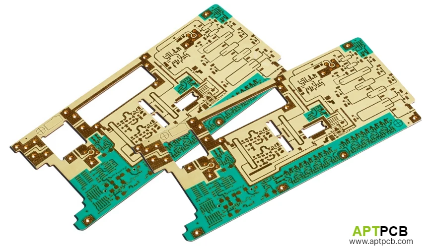
A "standard" Rogers RO3003 board doesn't exist—not in any commercially useful sense. Every RF front end, phased-array antenna module, or mmWave transceiver arrives at the PCB with a unique set of constraints: different RFIC footprints, different thermal budgets, different antenna array geometries, and different assembly processes. Whether the application is 5G infrastructure, automotive radar, Ka-band satellite terminals, or E-band backhaul links, the substrate has to be engineered around those constraints before a drill touches copper.
This is what custom RO3003 PCB design actually means. Not just specifying the material—but engineering the stackup layer by layer, selecting copper foil profile to match RF loss requirements, defining impedance targets with fabrication tolerances that close the link budget, and building DFM checkpoints into the design before fabrication begins.
Why Customization Starts at the Stackup
The stackup is the single most consequential design decision on an RO3003 program. It determines thermal performance, insertion loss, via aspect ratio, assembly yield, and raw material cost—all before any trace is routed.
For context on why the material behaves differently from standard laminates, the fundamental electrical and mechanical properties of Rogers RO3003 establish the baseline: Dk 3.00 ± 0.04 at 10 GHz, Df 0.0010, TcDk −3 ppm/°C, and Z-axis CTE of 24 ppm/°C. The custom stackup has to exploit these properties where they're needed and compensate for them where they're not.
Full RO3003 vs. Hybrid Construction
The first customization decision: does the entire board use RO3003, or only the RF layers?
Full RO3003 monolithic construction is appropriate for boards where the entire signal stack must maintain millimeter-wave integrity—high-density phased arrays where all routing layers carry RF signals, or modules with extremely tight Z-axis dimensional requirements. Material cost is maximum, but there's no hybrid bonding interface to manage.
Hybrid RO3003/FR-4 construction is the production standard for cost-sensitive RF programs. RO3003 on outer RF layers, high-Tg FR-4 on internal signal and power distribution layers. The raw material cost drops by 30–45% relative to full-RO3003 construction, and electrical performance on the antenna and feed layers is unchanged. The manufacturing complexity falls entirely on the fabricator, not the design.
As the RO3003 PCB supplier guide details, hybrid stackup cost optimization is the standard commercial approach—and one where working with a fabricator that has documented hybrid lamination capability matters directly to yield.
Custom Stackup Configuration: Layer-by-Layer Decisions
RO3003 Core Thickness Selection
Standard RO3003 cores are available in 5 mil (0.127mm), 10 mil (0.254mm), and 20 mil (0.508mm). Each drives a different set of trace geometry trade-offs for 50Ω microstrip across the mmWave frequency range.
| Core Thickness | ~50Ω Microstrip Width (1 oz Cu) | Application Fit |
|---|---|---|
| 5 mil (0.127mm) | ~4–5 mil | Dense array feed networks; tight pitch constraints |
| 10 mil (0.254mm) | ~9–11 mil | General mmWave RF layers; most manufacturable |
| 20 mil (0.508mm) | ~18–22 mil | Power handling; lower-frequency RF structures |
The 10 mil core is the most manufacturable choice for general mmWave programs. The ~10 mil trace width is practical to etch, inspect under 3D AOI, and repair in prototype stages. Thinner cores require LDI-calibrated etch compensation to hold trace width tolerances and produce via aspect ratios that challenge IPC Class 3 plating requirements.
Copper Foil: Low-Profile Is Not Optional at mmWave Frequencies
At millimeter-wave frequencies, the skin effect limits current flow to the outermost 1–2 μm of the conductor. Standard electrodeposited (ED) copper has RMS surface roughness of 5–7 μm—forcing current to follow a tortuous surface path and adding 30–40% more conductor loss than a smooth substrate would produce.
For mmWave custom PCB programs, APTPCB sources RO3003 pre-laminated with low-profile ED copper (Ra ≈ 1.5 μm) or Reverse Treated Foil (RTF). This is a laminate procurement specification—it must be defined before the material is ordered, not corrected after fabrication. If your design file doesn't explicitly call out copper foil profile on RF layers, ask what the manufacturer is ordering.
Inner Layer Material Selection for Hybrid Stackups
Not all FR-4 inner layer materials perform equally in hybrid lamination. The bonding film at the RO3003/FR-4 interface is a process-critical specification: standard FR-4 prepreg flows too aggressively under lamination pressure and can deform fine RF traces on adjacent RO3003 layers. Low-flow, high-Tg (>170°C) thermoset prepregs are required—a material specification that a custom PCB supplier must have validated in their hybrid lamination process before your program enters fabrication.
Impedance Customization: Closing the Link Budget in Fabrication
At RF and mmWave frequencies, the difference between a 48Ω line and a 50Ω line is not a minor tuning adjustment—it's a reflection that adds directly to path loss. Custom impedance design for RO3003 requires specifying three things precisely: the target impedance, the tolerance, and the test method.
Microstrip vs. Stripline Trade-offs on Custom RF Layers
Microstrip (trace on outer layer, reference plane below): The standard configuration for mmWave antenna feed networks. Simpler to model with electromagnetic simulators. Exposed to the environment, so surface finish affects insertion loss. APTPCB recommends Immersion Silver (ImAg) for outer-layer microstrip: the thin, flat deposit is electromagnetically transparent, unlike ENIG's 3–5 μm nickel underlayer, which adds measurable insertion loss at higher frequencies.
Stripline (trace buried between two reference planes): Lower insertion loss for a given trace length (shielded geometry reduces radiation loss). Better EMI containment. Via transitions require careful design—the transition from microstrip to buried stripline and back introduces parasitic inductance that must be accounted for in the EM simulation.
For phased-array feed networks where all element paths must arrive in-phase, buried stripline with matched via transitions is worth the added complexity. For simpler point-to-point front ends, outer-layer microstrip with controlled ImAg finish is the practical choice.
Differential Pairs and Common-Mode Impedance
Modern RFICs increasingly use differential signal architectures for improved common-mode noise rejection. Custom differential pair routing on RO3003 requires:
- Differential impedance target (typically 100Ω) specified separately from single-ended (50Ω) structures
- Intra-pair spacing matched throughout the routing with <0.1 mil variation
- Equal-length routing to within the dielectric wavelength tolerance at the operating frequency
- Reference plane continuity—no splits or cut-outs beneath differential pairs
TDR test coupons on the production panel must validate both single-ended and differential structures. A TDR report showing only 50Ω single-ended data doesn't confirm differential impedance.
Custom Via Structures: POFV, Blind, and Thermal Arrays
POFV (Plated Over Filled Via) for Thermal Pad Components
Every RF transceiver IC with an exposed thermal pad requires a POFV array beneath it. The standard FR-4 via-in-pad process doesn't transfer directly to RO3003—the fill material, surface planarity requirements, and PTFE drilling parameters all require customization. APTPCB targets POFV surface planarity within ±10 μm of the surrounding copper layer; deviations beyond this cause solder paste volume distribution problems and the voiding that subsequent 3D X-ray inspection will reject.
The thermal management challenges specific to RO3003 PCB manufacturing describe in detail why POFV array design is inseparable from the thermal management strategy: each copper via barrel conducts at ~398 W/m/K through a dielectric conducting at 0.50 W/m/K, and the array density directly determines junction temperature under the RFIC.
Blind and Buried Vias in Hybrid Stackups
Blind vias (connecting outer RO3003 layer to first FR-4 inner layer) reduce the via stub length that would appear in a full through-hole design—via stubs create unwanted resonances that degrade in-band performance at millimeter-wave frequencies. For hybrid custom designs operating above 60GHz, blind via transitions from the RF outer layer to the first inner reference plane are worth specifying.
The aspect ratio constraint on blind vias in PTFE is tighter than FR-4: APTPCB's maximum blind via aspect ratio for RO3003 layers is 0.8:1 (diameter:depth) to maintain plating coverage per IPC Class 3 requirements. Via diameter must be selected with this constraint in mind during custom stackup development.
Custom Cavity and Machining Options
Some custom RO3003 programs require physical features that go beyond standard planar construction:
Routed cavities for component embedding: Controlled-depth routing into the RO3003 outer layer to recess components below the board surface. Used in low-profile phased array modules where antenna element height above the ground plane must be precisely controlled. Requires diamond-tipped tooling and controlled routing depth (±25 μm tolerance achievable with CNC precision routing).
Precision edge trimming for phased array boards: Arrays where the antenna elements extend to the board edge require burr-free, precisely dimensioned edge profiles to maintain consistent element-to-element spacing at the physical boundary of the array. APTPCB's controlled routing achieves edge profile tolerances of ±0.1mm on RO3003 panels.
Back-drilling for stub elimination: Where through-holes are used and via stub resonance is a concern, back-drilling removes the non-functional portion of the via barrel below the last connected layer. Back-drill depth accuracy of ±50 μm is required to remove the stub without compromising the adjacent layer connection.
DFM Checkpoints Before Custom Fabrication
Custom RO3003 programs benefit from structured DFM review at two stages: before Gerber submission and after stackup finalization.
Pre-Gerber DFM (stackup review stage):
- Confirm core thickness and copper foil profile are specified and in-stock
- Validate hybrid bonding film compatibility with both materials
- Confirm thermal via array coverage (>50% of thermal pad area)
- Review drill aspect ratios against IPC Class 3 plating limits
- Validate minimum trace/space against LDI process capability
Post-Gerber DFM (fabrication file review):
- TDR test coupon placement on panel
- Etch compensation factors for copper foil type
- Bow/twist management: FR-4 inner layer copper density >75%
- Impedance structure documentation for test coupon mapping
APTPCB provides no-cost DFM review for RO3003 custom programs. The review outputs include a stackup confirmation, impedance simulation cross-check, and fabrication-to-design tolerance analysis before any material is ordered.
Rogers Circuit Board vs. Generic PTFE: Why the Distinction Matters in Custom Programs
"Rogers circuit board" and "generic PTFE composite board" are not interchangeable in any serious RF program—but the distinction is most critical in custom designs where specific dielectric properties are baked into the EM simulation.
Custom antenna arrays are designed with Dk 3.00 ± 0.04. A substitute material might spec Dk 3.0, but without the ceramic loading that stabilizes the value against temperature and manufacturing lot variation, the physical board won't match the simulation. Beam-steering accuracy degrades in ways that can't be compensated in firmware.
Rogers Corporation is the sole manufacturer of RO3003 laminate, and authentic material moves through Rogers-authorized distribution channels. APTPCB's sourcing is direct from Rogers or Rogers-authorized distributors, with Certificates of Conformance and lot number documentation provided as standard deliverables on every custom program.
Getting a Custom RO3003 Quote
Custom RO3003 programs require more information than standard FR-4 quotes. To receive an accurate quote and DFM feedback, provide:
- Layer stackup with all material specifications (core thickness, copper weight, copper foil profile)
- Gerber files or preliminary layout with controlled impedance structures identified
- Drill file with via types (through, blind, POFV) and fill requirements
- Surface finish specification (ImAg preferred for mmWave RF; ENIG if inventory storage is a factor)
- IPC class requirement (Class 3 for automotive)
- Quantity and delivery requirement (prototype, pilot, production)
Contact APTPCB's RF engineering team to begin a custom RO3003 DFM review or request a stackup consultation before your layout is finalized.
References
- Dk, Df, and copper foil specifications from Rogers Corporation RO3000® Series Circuit Materials Datasheet (Rev 11.2023).
- Via aspect ratio and plating requirements per IPC-6012 Class 3.
- Impedance tolerance and TDR test method per IPC-2141A Design Guide for High-Speed Controlled Impedance Circuit Boards.
- Etch compensation methodology per APTPCB High-Frequency PTFE Fabrication Control Plan (2026).