If you've landed on Rogers RO3003, you're probably designing something that operates above 20GHz—a 77GHz automotive radar, a 5G mmWave module, a phased-array antenna. This guide covers what the material actually is, what its datasheet numbers mean in practical RF terms, and how to decide whether RO3003 is the right substrate or whether something less expensive will serve you just as well.
What Problem RO3003 Solves
The core issue at millimeter-wave frequencies is that standard FR-4 epoxy-glass is electrically unstable. Its dielectric constant (Dk) varies by ±10% or more across the board, with frequency, and with temperature. Its dissipation factor (Df) sits around 0.020—twenty times worse than RO3003. At 1GHz, these are inconveniences. At 77GHz, they're design-ending.
Rogers RO3003 addresses both problems through material chemistry. It's a PTFE (polytetrafluoroethylene) matrix loaded with precisely controlled ceramic micro-particles. The PTFE delivers low loss. The ceramic loading stabilizes the dielectric constant against frequency and temperature changes, and restrains the polymer's natural thermal expansion to something compatible with copper and with via plating. It belongs to the same family of materials used across the broader microwave PCB spectrum—from X-band radar through Ka-band satellite links—but RO3003's specific Dk of 3.00 makes it the dominant choice for 77GHz automotive bands in particular.
The result is a substrate that behaves the way an EM simulation predicts—across the whole board, across the automotive temperature range, in production quantities. Translating those simulation results into fabrication-ready Gerbers is a separate discipline; the 77GHz Rogers circuit board design process covers how stackup tolerances, via geometry, and copper foil selection feed into whether hardware matches the model.
Key Electrical Specifications
| Property | Value | Test Condition |
|---|---|---|
| Dielectric Constant (Dk) | 3.00 ± 0.04 | IPC-TM-650 2.5.5.5 @ 10 GHz |
| Dissipation Factor (Df) | 0.0010 | IPC-TM-650 2.5.5.5 @ 10 GHz |
| Thermal Coefficient of Dk (TcDk) | −3 ppm/°C | −50°C to 150°C @ 10 GHz |
| Volume Resistivity | 10⁷ MΩ·cm | IPC-TM-650 2.5.17.1 |
| Surface Resistivity | 10⁷ MΩ | IPC-TM-650 2.5.17.1 |
Dk 3.00 ± 0.04: What This Means for Phased Arrays
In a phased-array antenna, all signal paths feeding the individual antenna elements need to arrive in phase. Phase velocity is proportional to 1/√Dk. When Dk drifts across a board, the paths arrive out of phase, and the radar's beam-steering accuracy degrades proportionally.
RO3003's ±0.04 tolerance is a ±1.3% variation around Dk=3.00. Tight enough that antenna simulations translate reliably into physical hardware. For engineers working on 77GHz radar front ends or multi-element arrays—the kind covered in depth on our RF and high-frequency PCB design guide—this predictability is what makes phased-array designs manufacturable at scale.
Df 0.0010: The Insertion Loss Arithmetic
Dielectric loss accumulates along every trace. The relationship:
Loss (dB/inch) ≈ 2.3 × f(GHz) × √Dk × Df
At 77GHz with RO3003 (Dk=3.00, Df=0.0010): roughly 0.31 dB/inch of dielectric loss.
Same calculation for FR-4 (Df≈0.020): approximately 6.2 dB/inch.
On a 3-inch feed network, that's the difference between 0.9 dB of substrate loss and 18.6 dB. The second scenario exhausts your entire link budget before the signal reaches the antenna elements. This is why FR-4 simply isn't a consideration for 77GHz front ends, and why RO3003's Df value is the primary reason it gets specified.
TcDk −3 ppm/°C: All-Weather Reliability Without Software Compensation
The TcDk tells you how much Dk drifts per degree Celsius. Over the −40°C to +85°C automotive operating range (125°C swing), RO3003's Dk changes by 0.000375. In antenna terms: essentially nothing.
Materials with TcDk values of 50–200 ppm/°C require active temperature compensation algorithms in the radar's baseband processor to correct for the frequency drift as the vehicle moves between environments. RO3003's −3 ppm/°C makes that compensation unnecessary, simplifying software architecture and eliminating a potential failure mode.
Key Mechanical and Thermal Specifications
| Property | Value | Test Method |
|---|---|---|
| CTE (X / Y / Z) | 17 / 16 / 24 ppm/°C | IPC-TM-650 2.4.41, −55°C to 288°C |
| Thermal Conductivity | 0.50 W/m/K | ASTM E1461 @ 80°C |
| Moisture Absorption | 0.04% | IPC-TM-650 2.6.2.1, 48h @ 50°C |
| Peel Strength (1 oz Cu) | 1.8 N/mm | After Solder Float, IPC-TM-650 2.4.8 |
| Flammability | V-0 | UL 94 |
CTE Matching: Protecting Trace Geometry Through Thermal Cycles
Copper's X/Y CTE is approximately 17 ppm/°C. RO3003 matches it: 17 ppm/°C on X, 16 ppm/°C on Y. This means the traces and substrate expand and contract together through automotive thermal cycling. The impedance-critical trace widths stay accurate.
The Z-axis CTE at 24 ppm/°C is also well-controlled. Pure PTFE without ceramic loading can exceed 200 ppm/°C in the Z-axis—an enormous mismatch with copper-plated vias that would cause barrel fractures during the first assembly reflow. The ceramic loading is specifically what brings this into a range where via reliability is achievable.
RO3003 vs. Alternatives: Decision Framework
Not every RF application requires RO3003. Here's where the material boundaries actually sit:
Use RO3003 when:
- Operating frequency is above 20GHz
- Phase coherence across multiple antenna elements is critical
- Automotive-grade qualification (IATF 16949, AEC-Q200) is required
- Insertion loss budget is tight—particularly on receive-path feed lines
Consider RO4350B or RO4003C (hydrocarbon-ceramic) instead when:
- Frequency is in the 3–18GHz range
- FR-4-compatible lamination processes are preferred for cost
- Dk tolerance of ±0.05 is acceptable for the application
FR-4 is not viable when:
- Frequency exceeds 5GHz with meaningful trace lengths
- Phase matching across multiple antenna elements is required
- Wide operating temperature range matters
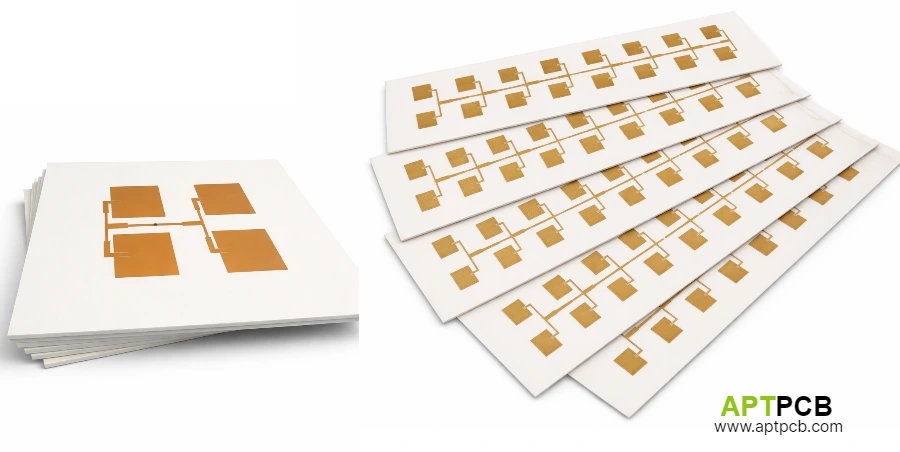
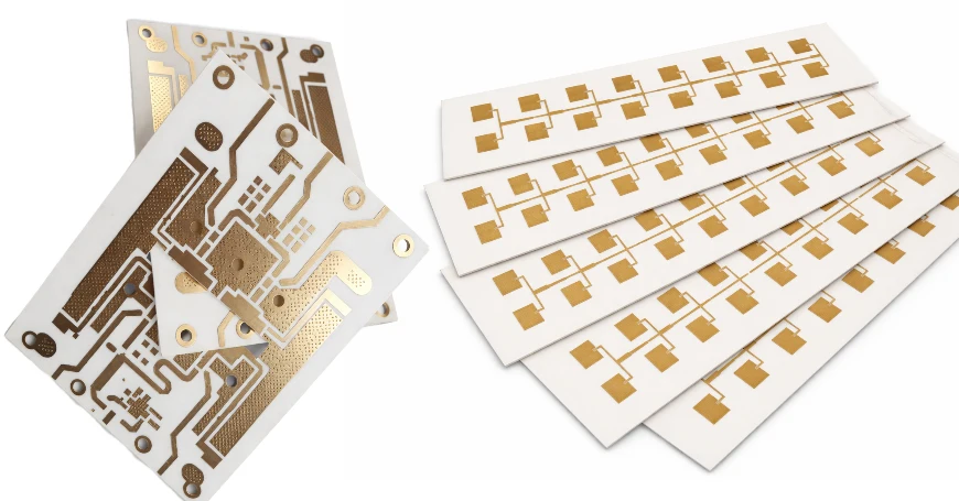
For mmWave antenna boards specifically—including array designs where the dielectric backing is part of the radiating structure—our antenna PCB manufacturing page covers how material selection, cavity machining, and surface finish interact with antenna gain and bandwidth.
Copper Foil Selection: Low-Profile Foil for Millimeter-Wave
At 77GHz, the skin effect limits current flow to the outermost 1–2 μm of the copper trace surface. Standard electrodeposited (ED) copper has RMS surface roughness of 5–7 μm. At those frequencies, that roughness forces current to travel a longer effective path—like water following a mountain terrain instead of a flat road. The result is 30–40% more conductor loss than a smooth surface would produce.
For 77GHz programs, APTPCB sources RO3003 laminated with low-profile ED copper (Ra ≈ 1.5 μm) or Reverse Treated Foil (RTF). This is a material procurement decision, not a post-processing fix—it has to be specified before the laminate is ordered.
If your manufacturer isn't explicitly specifying copper profile on your RF layers, ask.
Standard Core Thicknesses for 77GHz Designs
Rogers produces RO3003 in several standard core thicknesses. The most commonly used for 77GHz hybrid radar stackups:
- 5 mil (0.127mm): Thin outer RF layers; produces compact trace widths suitable for dense antenna arrays
- 10 mil (0.254mm): Most common for 77GHz RF layers; 50Ω microstrip requires approximately 9–11 mil trace width—practical to etch, inspect, and repair
- 20 mil (0.508mm): Where electrical length is a design variable, or power handling in the transmit chain is a concern
All thicknesses are available with 0.5 oz, 1 oz, or 2 oz copper in low-profile or standard foil configurations. Selecting the right combination for a specific antenna architecture—and defining the hybrid layer structure around it—is the starting point for any custom RO3003 stackup design.
Assembly Recommendations
RO3003 handles SMT assembly reliably with a few adjustments from standard FR-4 profiles:
- Peak reflow temperature: 260°C maximum; profiling to 245–250°C peak is recommended to reduce thermal stress on the PTFE-copper interface
- Time above liquidus: 30–45 seconds target
- Surface finish: Immersion Silver (ImAg) preferred for 77GHz RF layers—its thin, flat deposit preserves the low-roughness copper surface. ENIG adds a 3–5 μm nickel layer that increases insertion loss measurably at millimeter-wave frequencies
- Multiple reflow passes: Limit to two passes above 220°C where possible
Manufacturer Capability Is Part of the Spec
RO3003 on a drawing is not the same as RO3003 correctly processed. PTFE requires vacuum plasma surface modification before copper plating bonds to via walls. The ceramic-loaded matrix requires modified drilling parameters. Hybrid stackups that combine RO3003 with FR-4 require precise lamination cooling rate control to prevent panel warpage.
These requirements eliminate the majority of standard PCB fabricators from consideration. Before locking in a manufacturer for a 77GHz program, verify that they have in-house plasma desmear capability, LDI imaging for RF layer etching, and documented IPC Class 3 plating results on PTFE substrates. The step-by-step PTFE fabrication process—from modified drilling parameters through vacuum plasma activation to hybrid lamination—explains why each of these requirements exists and what to look for when verifying them.
Submit your RO3003 stackup to APTPCB's engineering team for a DFM review before ordering materials or committing to a prototype run. For programs that are still evaluating suppliers, the RO3003 PCB manufacturer capability checklist provides the specific verification questions—plasma equipment, IATF certification, and microsection documentation—that separate qualified PTFE fabricators from those applying FR-4 processes to the wrong material.
Normative References
- Electrical specifications from the Rogers Corporation RO3000® Series Circuit Materials Datasheet (Rev 11.2023).
- Copper roughness and skin-effect insertion loss methodology per IPC-2141A Design Guide for High-Speed Controlled Impedance Circuit Boards.
- Manufacturing and assembly protocols per APTPCB's High-Frequency PTFE Fabrication Control Plan (2026) and IPC-A-600K Class 3 acceptance criteria.