
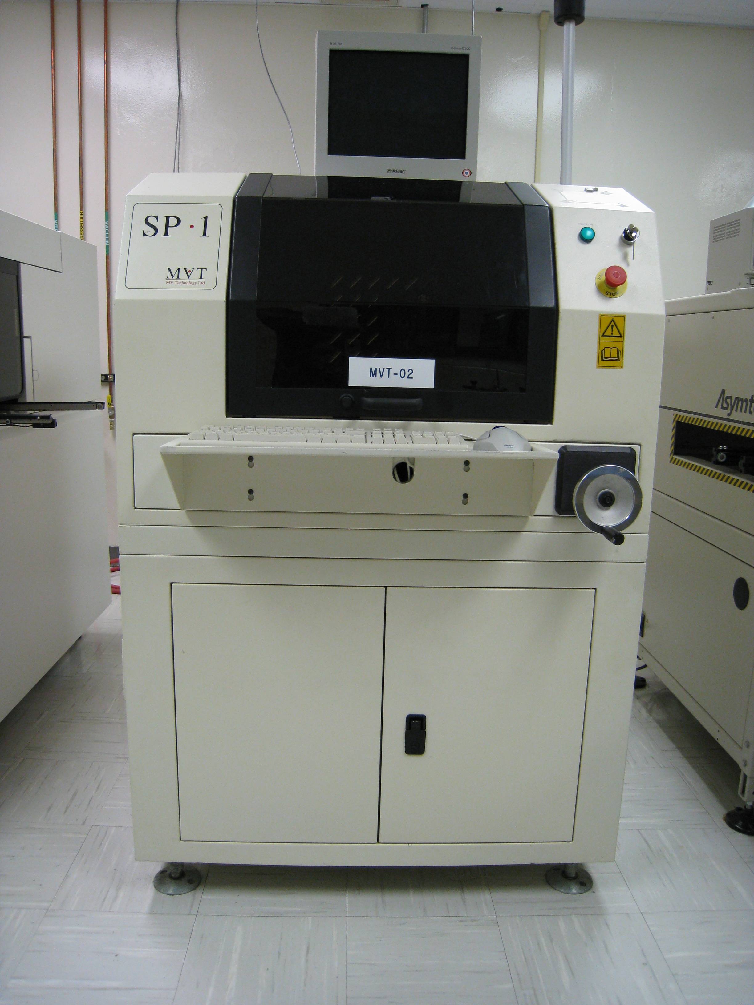
Solder paste inspection (SPI) checks paste deposits after stencil printing and before component placement. Its measurements can help an SMT engineer distinguish a localized printing problem from a shift affecting much of a panel.
For an assembly buyer, SPI evidence can show what was inspected, which criteria were applied and how suspect boards were handled. That evidence needs to be agreed with the assembler; an inspection requirement alone does not define the report or guarantee coverage.
What SPI measures
Depending on the equipment, program and measurement method, an SPI system may report deposit characteristics such as:
- Area: the measured footprint of a deposit.
- Position or offset: where the deposit lies relative to a programmed reference.
- Height: the measured height of paste above a reference plane.
- Volume: an estimated deposit volume derived from measured dimensions.
A 2D inspection method primarily evaluates information from an image in a plane, such as deposit area and position. It does not by itself provide the height information needed to estimate volume in the same way as a 3D measurement method. A 3D method adds height information, but its reported values still depend on how the system measures, registers and processes the deposit.
The IPC-hosted experimental paper Solder Paste Inspection Technologies: 2D-3D Correlation is a useful primary-source reference for considering these measurement approaches. Its limited experiment is not a product acceptance standard.
SPI describes the print at the inspection stage. It does not establish what the finished solder joint will look like after placement and reflow.
The paste itself is another input to the printing process. The solder paste selection guide covers material and handling considerations to discuss with the assembler.
Read the reference before the percentage
An SPI percentage has meaning only when its denominator is known. A volume result expressed as a percentage, for example, is relative to a reference volume configured or used by the inspection program. Do not assume that the reference is always derived from the pad, stencil aperture or another nominal value: confirm its source and the program revision.
Hypothetical calculation: if the programmed reference volume for a deposit is 0.020 mm³ and the measured volume is 0.016 mm³, the reported value relative to that reference is 80%. That calculation does not say whether the deposit is acceptable. Acceptance depends on the agreed criteria for that location and the reliability of the measurement.
Ask the same reference question for area and offset results. Also check the units, whether the report shows individual deposits or summaries, and whether a value represents a single reading or an aggregate.
Separate three questions in the report
A useful SPI review keeps product acceptance, process trends and measurement reliability distinct.
| Question | What to examine | What it does not establish on its own |
|---|---|---|
| Is this deposit acceptable? | The measured value against the agreed criterion for that location | Whether the process is stable over time |
| Is the process changing? | Patterns across locations, panels and successive prints | Whether every individual deposit meets its criterion |
| Is the measurement trustworthy? | Program and reference, registration, board support and other conditions relevant to the system | That a low or offset reading has a particular physical cause |
A process can show a trend before an individual reading fails its agreed criterion. Conversely, an apparent failure should be investigated rather than dismissed as a measurement issue. Where measurement reliability is in doubt, contain the affected panels while the team verifies the setup and readings.
Worked example: investigate panel by panel
The following investigation is hypothetical. The observations, checks and dispositions are examples, not APTPCB results or universal acceptance rules.
1. Start with the suspect panel
An SPI report flags low volume at several nearby deposits on Panel 1. Other deposits on the same panel do not show the same pattern.
Before attributing the readings to printing, the engineer checks:
- The correct inspection program and revision are loaded.
- The flagged deposits use the intended references and acceptance criteria.
- The panel is registered correctly for inspection.
- Board support is appropriate and the panel is presented consistently.
The team contains Panel 1 while it reviews the readings. A localized print issue is one hypothesis; an incorrect reference, registration problem or support-related measurement issue is also possible. None is yet a proven cause.
2. Compare the next panel’s pattern
Panel 2 shows a different pattern: deposits across several locations appear shifted in a similar direction relative to their programmed positions.
The engineer checks whether the apparent common offset is consistent with the physical print or could arise from panel registration in the inspection setup. A printer alignment issue is a hypothesis, not a conclusion from the report alone. Panel 2 is also contained pending review.
Comparing the panels matters: nearby low-volume readings and a panel-wide apparent offset are different observations, even if both result in an SPI alert. They should not automatically receive the same correction.
3. Check the print and verify the next panels
After the team investigates the relevant setup and makes any approved adjustment, it inspects the next printed panels using the verified program and references. It compares the previously flagged locations and the broader position pattern with the agreed criteria.
The team records the new readings before deciding whether the response resolved the observed variation.
4. Record disposition
For each contained panel, the team records its identity, the issue observed, the checks performed, the applicable criteria and the authorized disposition. Any removal, reprint, reinspection or other handling follows the agreed process. The record should distinguish a confirmed finding from a suspected cause.
Example: connect a reading to its disposition
The following record is invented to show what a buyer and assembler can agree to retain. It is not an APTPCB report, a recommended limit, or a record of a production run.
- Product and panel: Project K, Panel 1, top side.
- Program and location: Revision P3, deposit U1-12.
- Volume and reference: 0.016 mm³ against 0.020 mm³, or 80%. The program should identify the reference used.
- Initial result: The example program alerts below 85%; 80% is flagged and the panel is held.
- Review and disposition: Registration and program checked; disposition pending.
The 85% alert is a made-up condition for this record, not an acceptance limit or recommended setting. If the panel is cleaned and reprinted under an approved process, retain the original call and add the reinspection result and authorized disposition. If it is accepted, identify who made that decision and against which requirements. Ask whether the inspection program includes the gaps between deposits as well as the deposits themselves; coverage depends on the setup.
How SPI fits with later inspection
SPI answers questions about the paste print before placement. Other checks address different stages or risks:
- AOI can inspect visible assembly features at a later stage, according to its program and coverage.
- X-ray inspection can be used to examine features that require an appropriate internal-view method; suitability and coverage should be confirmed for the assembly.
- Electrical testing checks specified electrical behavior. It does not replace a record of the paste print.
These methods are complementary, not interchangeable. For a stage-by-stage comparison, see SPI vs. AOI in PCB assembly and AOI and SPI inspection ownership.
SPI data may support a process reaction, but do not assume that an inspection system automatically adjusts the printer or that every defect will be detected. Confirm the inspection and response workflow with the assembler.
What buyers should specify
Before production, agree on the inspection scope and the evidence needed for decisions. At minimum, discuss:
- Scope and coverage: Which sides, panels and deposit locations are inspected? Are critical locations identified?
- Identification: How will the report link results to the product, panel, side and production run?
- Program and references: Which program revision and reference values apply?
- Acceptance: What criteria apply to each relevant measurement and location?
- Sampling: Which panels are inspected, and when?
- Failed-board disposition: How are affected panels contained, reviewed and released or otherwise handled?
- Requested report: Can it include individual readings, percentages and their references, flagged locations, images, trend information and disposition records? Which items are feasible for this assembly?
Confirm feasibility and coverage with the assembler rather than assuming that every requested field is automatically available. An assembly drawing can help identify critical locations and communicate inspection needs.
For a discussion of the inspection service, see SPI inspection. To specify the broader verification plan, review PCB assembly testing and quality.
Include your proposed SPI scope and reporting requirements with a quote request, or contact APTPCB to discuss feasibility.