
For a PCB quotation, the useful question is not simply “Is this 1 oz copper?” It is whether 1 oz describes the starting foil or the finished conductor, and whether the design also needs a measurable minimum thickness.
Use copper weight as a nominal reference. If a conductor needs a specific finished thickness, put that requirement on the fabrication drawing for the affected layer, along with where and how it will be checked. Keep plated hole-wall copper and surface finish separate.
Copper weight to thickness chart
PCB copper weight is commonly expressed in ounces per square foot (oz/ft²): the mass of copper distributed over an area. It is not the total copper mass on the board.
The chart below uses a deliberately rounded convention of 35 µm per oz/ft². It is a nominal reference, not a minimum finished-copper table, tolerance table, or statement of APTPCB availability.
| Copper weight, oz/ft² | Reference thickness, µm | Reference thickness, mm | Reference thickness, mil |
|---|---|---|---|
| 0.5 | 17.5 | 0.0175 | 0.69 |
| 1 | 35 | 0.035 | 1.38 |
| 2 | 70 | 0.070 | 2.76 |
| 3 | 105 | 0.105 | 4.13 |
| 4 | 140 | 0.140 | 5.51 |
The arithmetic used throughout the chart is:
- µm ≈ 35 × copper weight in oz/ft²
- mm = µm ÷ 1,000
- mil = µm ÷ 25.4
For example, on this basis, 2 oz/ft² is approximately 70 µm, or 2.76 mil. The mil values are rounded; a mil is one thousandth of an inch.
The 35 µm basis is a convenient convention, not an exact physical conversion. An ideal uniform layer calculated using a copper density of 8.96 g/cm³ gives approximately 34.1 µm per oz/ft². Other documents use other rounded references. When comparing numbers, check the stated basis rather than treating the last decimal place as a manufacturing guarantee.
Copper thickness is also different from the finished thickness of the whole board. For that mechanical dimension, see standard PCB thickness.
Base copper and finished copper are different requirements
Base copper is the starting foil associated with a layer before the relevant fabrication operations. Its nominal weight helps describe the construction, but the actual starting foil thickness need not equal the rounded chart value at every point.
Finished conductor copper is the copper remaining in the conductor after the applicable addition and removal steps. Depending on the layer and build, the final thickness can differ from the starting foil.
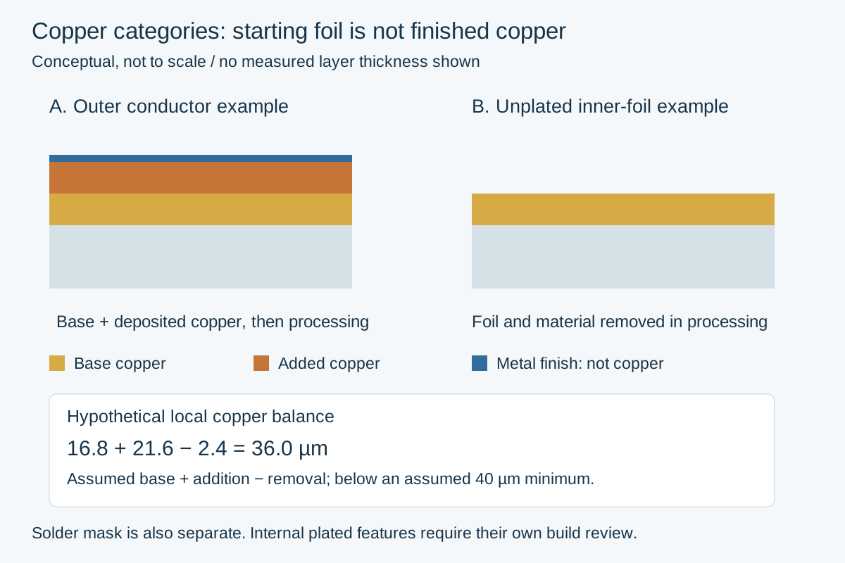
Conceptual illustration, not a measured stackup or a drawing to scale. Base copper, added copper, inner foil, and surface finish are different categories.
An outer layer in a plated-hole build can receive additional copper during fabrication. It can also lose copper during later processing. Texas Instruments’ SPMA056 gives one specific four-layer example in which outer signal layers use nominal half-ounce base copper plus half-ounce plating to describe a nominal one-ounce total. That example shows why a “1 oz outer layer” label does not necessarily mean the board started with 1 oz foil. It is not a universal plating recipe or finished-copper minimum.
An ordinary inner layer is often patterned from foil without the same outer-layer plating sequence. For that construction, the starting foil and material removed during processing are important to the finished result. Do not extend that description to every board: sequential and other complex builds can include plated internal features. Identify those features and their requirements in the build documentation.
A numerical example: close to nominal is not the same as passing a minimum
Assume a local outer conductor has these illustrative actual values:
- Starting copper: 16.8 µm
- Copper added: 21.6 µm
- Copper removed later: 2.4 µm
The simplified result is:
16.8 + 21.6 − 2.4 = 36.0 µm finished copper
That result is close to the chart’s 35 µm nominal reference for 1 oz. But if the project separately requires a 40 µm minimum at that defined measurement location, 36.0 µm fails that numerical bound.
The 40 µm requirement and all three process values are assumptions for this example—not an industry threshold, an APTPCB production result, or a prediction of a particular process. The point is contractual as well as numerical: a nominal label and a minimum acceptance value answer different questions.
Keep planar copper, hole walls, and finish separate
A conductor on a board layer and the copper deposited on a plated hole wall are related to the build, but they are not interchangeable dimensions.
Specify planar conductor thickness for the relevant layer and location. If hole-wall copper matters, state its requirement separately for the applicable holes and identify the governing inspection basis. Do not assume that a finished outer-layer copper number also describes the barrel wall.
Likewise, solder mask is not copper. A metallic surface finish such as nickel/gold or tin is a separate material system; do not count those metals as part of the copper thickness. Name the required finish separately on the drawing.
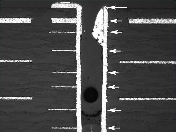
NASA coupon defect micrograph, credited to Charles E. Powers/NASA GSFC, 2009. The original arrows identify missing internal and external annular rings. This is not an APTPCB specimen; the image has no scale for determining copper thickness or acceptance. Image credit and source record.
A microsection can show conductor and hole-wall context, but an image alone is not a thickness requirement. A usable inspection plan identifies the feature, preparation and measurement method, sample, and acceptance basis.
Turn the chart into a layer-by-layer RFQ
Consider an assumed four-layer project. The design team needs at least 40 µm of finished copper at specified locations on L1. It has no separate numerical finished-copper minimum for the other planar layers beyond the project’s governing requirements.
The team proposes the following starting stackup for quotation. The base-foil values are proposed nominal values, not measured results or fixed process instructions. A fabricator may propose a different starting foil for review if that is needed to meet the finished requirement.
| Layer | Proposed nominal base foil | Finished planar copper requirement | Location, method, and acceptance record |
|---|---|---|---|
| L1 — outer | 0.5 oz/ft² | 40 µm minimum at the agreed locations | Identify representative L1 trace locations and agree on measurement method, sample and governing requirement before release |
| L2 — inner | 1 oz/ft² | No additional numerical minimum specified in this example | Identify the governing requirement and confirm the layer construction and quoted finished basis |
| L3 — inner | 1 oz/ft² | No additional numerical minimum specified in this example | Identify the governing requirement and confirm the layer construction and quoted finished basis |
| L4 — outer | 0.5 oz/ft² | No additional numerical minimum specified in this example | Identify the governing requirement and confirm the quoted finished basis |
This is an RFQ interpretation example, not a completed production drawing. In particular, the table does not establish that the proposed L1 starting foil will achieve 40 µm finished copper. It makes the distinction visible so the construction can be reviewed before the order is released.
For every layer, the requirement record should preserve:
- Layer ID that matches the stackup and artwork.
- Nominal base foil, including whether it is mandatory or a proposed construction.
- Finished-copper minimum or range, where the design needs a numerical limit.
- Measurement location, method, and sample, where acceptance depends on a measurement.
- Governing requirement, including the applicable document, revision, class if relevant, and agreed exceptions.
If a layer does not have a project-specific numerical minimum, that does not mean it has no requirements. The quotation still needs a defined finished-copper basis and the governing fabrication and acceptance requirements.
Example drawing note for L1
The following is a starting note for the assumed project, not a substitute for an agreed inspection plan:
L1: finished planar conductor copper shall be at least 40 µm at the designated L1 trace measurement locations. Proposed nominal base foil is 0.5 oz/ft²; an alternative construction requires design approval. Confirm the measurement method, sample or coupon relationship, governing specification and revision, applicable class, and exceptions before fabrication release. Specify plated hole-wall copper and surface finish separately.
The drawing must identify the designated locations and complete the governing references. If a representative coupon is proposed instead of the board itself, define how that coupon relates to the requirement being accepted. A cross-section may be an appropriate proposed method, but the feature, preparation, sampling, and measurement convention still need agreement.
Avoid writing “±35 µm” when you mean “approximately 35 µm.” A nominal reference, a tolerance around a target, and a minimum limit are three different instructions. If both a particular base foil and a finished minimum are genuinely mandatory, say so explicitly and have that combination reviewed. Otherwise, defining the finished requirement and allowing a reviewed construction gives the fabricator room to propose a suitable process.
For the rest of the drawing package, including how the stackup and notes fit together, see fabrication drawing essentials and PCB stackup design.
Compare quotations on the same basis
Two quotations can both say “1 oz” and still describe different things. Before choosing between them, compare the returned stackups and look for these distinctions:
- Base or finished? A base-foil designation is not equivalent to a finished-conductor minimum.
- Which layer? An outer plated layer and an ordinary inner foil layer can follow different process paths.
- Nominal or acceptance limit? A rounded finished reference does not by itself confirm the L1 40 µm minimum in the example.
- Where is it checked? A statement about a trace, pad, coupon, or hole wall needs the corresponding location and measurement basis.
- What else changed? A proposed copper construction change should be reviewed against the complete stackup and design requirements before release.
For the assumed project, the actionable outcome is a quotation that identifies the proposed base foil for each layer and explicitly addresses the L1 40 µm minimum at the agreed locations. If the proposed construction cannot meet that requirement, do not relabel a nominal 1 oz answer as compliant. Review an alternative construction or revise the requirement through the design approval process. If the measurement basis or governing document remains unresolved, keep that point open rather than treating the quotation as a confirmed acceptance commitment.
Copper thickness is one input to electrical and thermal design, but this chart does not establish current capacity. For that separate decision, see the heavy-copper PCB design guide.
Send the requirement with the stackup
For an APTPCB request, send the layer-by-layer copper record with the fabrication drawing, stackup, and design files. Mark which base-foil entries are proposals, identify any mandatory finished limits, and request that the returned quotation flag proposed changes and unresolved inspection points.
Start a quote with the project package, or contact APTPCB if the layer requirements need clarification before submission. The goal is a shared, project-specific definition of what will be built and how any stated limit will be evaluated.
Source basis
- LPKF, TechGuide: In-House PCB Prototyping, “Basic Information on PCBs.”
- Texas Instruments, SPMA056, Section 3.2.1 and Figure 4.
- NIST, Composition of COPPER and Handbook 44, Appendix C.
- NASA/GSFC, Charles E. Powers, 2009, NTRS 20090027819.