
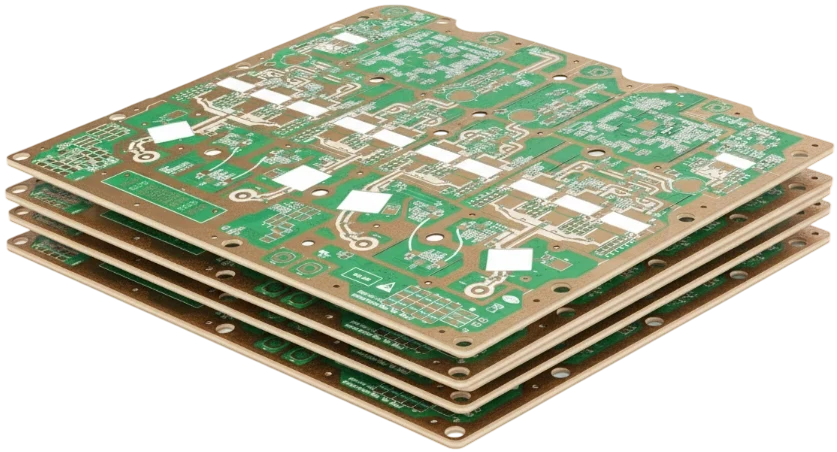
PCB color is determined entirely by the solder mask coating, not by the copper or base laminate. All common circuit board colors — green, matte black, high-reflectivity white, blue, red, and purple — utilize the same core liquid photoimageable (LPI) polymer chemistry infused with different organic and inorganic pigments. A green circuit board differs from a black circuit board solely in its photoresist ink formulation, not the underlying FR-4 glass-epoxy core.
While altering the mask color rarely degrades dielectric breakdown strength or surface insulation resistance, it drastically impacts photolithography exposure resolution, minimum solder mask dam widths, AOI defect escape rates, reworkability, and procurement lead times.
This engineering guide explains why the green printed circuit board became the undisputed manufacturing default, provides exact DFM dimensional limits (minimum solder mask dams and clearances) across each color, evaluates cost and schedule trade-offs, and details how to specify mask parameters in your fabrication drawing.
Key takeaways
- Why green is the baseline: Green LPI mask offers the widest photolithography exposure latitude, achieves the finest resolution (down to 3.5 mil / 0.09 mm solder mask dams), provides superior human/AOI optical contrast, and carries zero supplier surcharges or MOQ penalties.
- DFM resolution penalty for black and white: Black ink blocks UV penetration while white ink scatters light laterally. Both require expanding minimum solder mask dams to 4.5–5.0 mil (0.11–0.13 mm), which can prevent independent mask webs between fine-pitch (≤ 0.5 mm) IC pads and increase bridging risks.
- Black PCB trade-offs: Low visual contrast makes optical inspection and manual probing challenging; opaque black ink completely blocks backlit trace verification; higher infrared emissivity tightens convective reflow thermal profiles.
- White PCB for lighting: High-reflectivity white masks reflect 85% to 90% of visible light to maximize luminous efficiency in LED engines, but show flux residue distinctly and risk yellowing under repeated 260°C lead-free reflow peaks.
- Blue, red, and yellow: Excellent compromise for branded hardware, engineering prototypes, and system modularity, maintaining acceptable AOI contrast with 4.0 mil minimum dams.
Why are PCBs green?
Whether you search "why is PCB green", "why are circuit boards green", or wonder why the green printed circuit board default persists after decades of polymer development, the answer stems from photochemical physics and supply chain economics rather than aesthetics.
1. Photochemical maturity and curing depth
Early liquid photoimageable (LPI) formulations (such as Taiyo PSR-4000 series) were originally synthesized around green pigment dispersions. The absorption spectrum of green pigment aligns exceptionally well with the emission peaks of mercury-vapor exposure lamps and modern 365 nm / 405 nm Laser Direct Imaging (LDI) optics. UV light penetrates deeply through the liquid resin to the copper interface without scattering or premature surface attenuation, enabling clean undercut profiles and complete cross-linking through a 1.0 mil (25 µm) coating.
2. Optical contrast for human and automated optical inspection (AOI)
The human eye is most sensitive to green wavelengths (~555 nm), significantly reducing eye fatigue during manual assembly, microscopic inspection, and rework. More importantly, automated optical inspection (AOI) algorithms rely on spectral reflection ratios between bare copper (bright reddish-yellow), tin/ENIG plating (bright silver/gold), white silkscreen, and the dark base substrate. Green provides the highest dynamic range across monochromatic and RGB camera systems.
3. Supply chain volume loop
Because fabricators process green boards 24/7 on continuous curtain-coating, screen-printing, and spray lines, green ink requires no tank purging or screen changeover. Running a standard green PCB board incurs no setup surcharge, no minimum order quantity (MOQ) penalty, and zero schedule delay.
PCB solder mask colors compared
Selecting a solder mask color is an engineering decision balancing photolithography tolerances, inspection reliability, cosmetic requirements, and manufacturing cost.
| Solder mask color | AOI & visual contrast | Availability & cost | Typical applications |
|---|---|---|---|
| Green | Maximum contrast; traces, pads, and bridges resolve cleanly | Stock standard; zero surcharge | Default for 85%+ of commercial, industrial, and mil-aero boards |
| Black (Matte/Gloss) | Minimal contrast; copper traces concealed; requires dedicated AOI calibration | Common option; minor setup fee (+5–10%) | High-end consumer tech, audio equipment, stealth / proprietary designs |
| White | High contrast to dark components; shows flux residue and contamination | Common option; minor setup fee (+5–10%) | LED light engines, backlights, architectural lighting luminaires |
| Blue | High contrast; traces clearly visible; clean silkscreen legibility | Widely stocked; minimal fee | Development boards, modular add-on cards, corporate branding |
| Red | Medium-high contrast; distinct trace visibility | Widely stocked; minimal fee | Precision instruments, safety/critical boards, prototype runs |
| Purple, Yellow, Orange | Moderate contrast; requires color verification | Special order; MOQ & lead time impact | Limited boutique runs, signature developer hardware |
Manufacturing and DFM limits by solder mask color
The most critical—and frequently overlooked—difference between solder mask colors is their photolithographic resolution boundary.
During exposure and development, different pigment chemistries alter how photons penetrate the unpolymerized ink:
- Light absorption in black ink: Carbon black pigments heavily absorb UV photons. If exposure energy is insufficient, the base of the solder mask near the copper does not fully cure, leading to undercutting and solder mask dam lifting/flaking during chemical development.
- Light scattering in white ink: Titanium dioxide ($TiO_2$) pigments cause severe optical halation (lateral photon bounce). The scattered light cures regions under the mask artwork edges, causing hazy pad openings or narrowed clearances.
Because of these optical behaviors, fabricators enforce stricter Design for Manufacturing (DFM) design rules for non-green masks:
| Color specification | Min solder mask dam (Web) | Min pad clearance (Per side) | Backlit trace visibility | Fine-pitch IC compatibility (≤0.5mm pitch) |
|---|---|---|---|---|
| Standard Green | 3.5 – 4.0 mil (0.09–0.10 mm) | +2.0 mil (0.05 mm) | Excellent (semi-translucent) | Fully compatible with 0.4mm / 0.5mm BGA & QFN |
| Matte / Gloss Black | 4.5 – 5.0 mil (0.11–0.13 mm) | +2.5 – 3.0 mil (0.07 mm) | Completely opaque | Risk of dam peeling; often requires gang relief |
| High-Reflectivity White | 4.5 – 5.0 mil (0.11–0.13 mm) | +2.5 – 3.0 mil (0.07 mm) | Opaque | Halation risks; gang relief recommended for fine-pitch |
| Blue & Red | 4.0 mil (0.10 mm) | +2.0 – 2.5 mil (0.06 mm) | Moderate | Compatible with 0.5mm pitch ICs |
| Yellow & Purple | 4.5 mil (0.11 mm) | +2.5 mil (0.06 mm) | Good to moderate | Standard pitch only (≥0.65mm recommended) |
DFM Rule of Thumb: If your PCB layout features fine-pitch ICs (such as 0.4 mm pitch QFNs or 0.5 mm ball-pitch BGAs) where copper pad-to-pad spacing is under 8 mil, specifying a black or white solder mask may force the CAM engineer to remove individual solder mask dams and use gang mask openings (pocket relief), leaving bare laminate between adjacent pins and increasing the risk of solder bridging during reflow.
Does a black PCB board cost more than a green one?
A black PCB board typically incurs a modest setup fee (often $20–$50 per batch or a 5–10% square-meter surcharge) and can add 24 to 48 hours to prototype turnaround times when the coating line requires dedicated ink preparation and washdown.
Beyond procurement pricing, specifying a black circuit board introduces three real engineering costs:
- Optical inspection and repair barriers: Because copper, bare FR-4, and black mask have similar optical reflectance, AOI cameras must employ specialized angled ring lighting to distinguish solder bridges. Field repairs and oscilloscope probing become slower because internal traces cannot be visually tracked.
- Zero backlit transparency: On green or amber boards, test engineers place high-intensity flashlights behind the PCB (backlighting) to trace inner-layer tracks and locate drilled via misalignment. An opaque black circuit board completely blocks light transmission, eliminating this non-destructive diagnostic method.
- Reflow thermal profile narrowing: Black surfaces absorb higher levels of infrared and radiant convective heat than pale green or white boards. On densely populated boards with mixed thermal masses, black areas heat faster, narrowing the Delta-T ($ΔT$) margin between fragile plastic IC packages and high-thermal-mass copper ground pours.
What about white, blue, red, and purple circuit boards?
White circuit boards: Luminous efficiency vs. yellowing
A white PCB board is the standard choice for architectural, automotive, and commercial LED lighting. High-performance white formulations (such as Taiyo PSR-4000 WT series) achieve 85% to 90% optical reflectance across the 450–700 nm spectrum, effectively redirecting lost secondary lumens back through the optical diffuser.
However, white masks present distinct fabrication trade-offs:
- Flux stain visibility: Rosin and water-soluble flux residues appear as prominent brownish halos on white backgrounds, mandating aggressive PCBA post-reflow cleaning.
- Thermal yellowing: Prolonged operating temperatures exceeding 100°C or multiple lead-free reflow passes (260°C) cause conventional epoxy resins to yellow, degrading color temperature consistency in architectural luminaires. Specify automotive-grade, non-yellowing ceramic-filled white inks for high-power LED designs.
- Pair white mask decisions with substrate selection on our dedicated LED PCB guide.
Blue, red, and custom colors: Branding and functional segregation
Blue and red circuit boards represent the premier choices for branded dev-kits, modular daughterboards, and engineering prototypes. Both colors offer sharp optical contrast against white silkscreen while maintaining adequate transparency to inspect underlying copper tracks.
Purple, yellow, and orange masks are typically reserved for limited-edition hardware or developer-community branding. Because these inks have lower inventory turnover, confirm pigment availability with your manufacturer before committing to tight production schedules.
Matte vs glossy solder mask finishes
In addition to color, modern liquid photoimageable masks can be formulated with either a glossy or matte surface finish:
- Glossy solder mask: Features a smooth, glass-like reflective surface. Glossy finishes resist dust accumulation and handle mechanical handling scratches well, but can create intense optical glare under AOI inspection lamps.
- Matte solder mask: Incorporates microscopic silica matting agents that scatter incident light. The diffused surface eliminates AOI glare, hides fingerprints, and delivers an understated industrial aesthetic. However, matte finishes have a slightly softer surface hardness, making them marginally more susceptible to scratch marks during automated board depaneling and testing.
Neither finish alters dielectric breakdown voltage or moisture insulation resistance.
Does solder mask color change electrical performance?
Electrically, no. High-quality LPI inks across all colors deliver equivalent electrical insulation characteristics when fully cured:
- Dielectric breakdown voltage: > 500 V/mil (> 20 kV/mm)
- Volume resistivity: > 10^12 Ω·cm (IPC-TM-650 2.5.17)
- Dielectric constant ($D_k$): ~3.8 to 4.2 at 1 GHz
- Loss tangent ($D_f$): ~0.02 to 0.025 at 1 GHz
The differences remain purely optical, thermal, and photolithographic.
How to specify solder mask color in fabrication notes
To prevent CAM delays and ensure your board house delivers the exact finish required, document mask requirements unambiguously in your Master Fabrication Drawing (or Gerber Readme):
- State both color and finish explicitly: E.g.,
"Solder Mask: Liquid Photoimageable (LPI), Matte Black per IPC-SM-840 Class T"rather than simply"Black Mask". - Define fine-pitch dam priorities: If routing includes ≤0.5 mm pitch packages, state whether minimum 4.0 mil dams must be preserved or if gang mask relief is permitted.
- Specify non-yellowing white for LEDs: For lighting boards, specify
"High-reflectivity non-yellowing white LPI solder mask (R > 85%, Delta E < 3 after 3x reflow)". - Clarify via tenting and plugging: Note whether vias should be tented with mask, partially filled, or plugged with non-conductive epoxy before mask application.
When finalizing stack-up and finish notes, review your overall stack-up constraints on our multilayer PCB manufacturing page.
Frequently asked questions
Why are PCBs green instead of another color?
Green was the first photoimageable solder mask formulation to achieve mature process stability. It provides the highest optical contrast for AOI and human inspection, allows the narrowest solder mask dams (3.5 mil), and is stocked globally without surcharges.
Does a black circuit board cost more than a green one?
Yes, typically a 5% to 10% batch surcharge or small setup fee, plus potentially 1 to 2 additional production days for ink preparation and line purging. It also requires careful AOI tuning and prevents backlit trace inspection.
Can I use black solder mask on fine-pitch 0.4mm or 0.5mm BGA boards?
You can, but the fabricator may not be able to maintain isolated 4.5–5.0 mil solder mask dams between pads. They may need to merge the openings into a single gang relief pocket, which increases the likelihood of solder bridging during assembly. Green is strongly recommended for fine-pitch layouts.
Why do white LED circuit boards turn yellow over time?
Standard epoxy resins undergo photochemical degradation under sustained heat (>100°C) and short-wavelength light (blue/UV LEDs). High-reliability LED circuit boards require specialized ceramic-filled, non-yellowing white LPI formulations.
How do engineers inspect internal copper traces on black PCBs?
They cannot use standard backlighting. Visual trace inspection on black boards requires high-intensity top-down angled illumination or non-destructive X-ray inspection (AXI) and boundary scan testing.
Does solder mask color alter high-frequency RF impedance?
The solder mask pigment has virtually no effect on RF impedance. However, mask thickness variations over RF microstrip lines do affect effective dielectric constant ($ε_{eff}$). If designing RF circuits, specify tight solder mask thickness tolerances (e.g., 15 ± 5 µm) or leave RF traces unmasked.
Related resources
- What Is Solder Mask? Materials, Colors and PCB Rules — Comprehensive guide on solder mask materials, LPI vs dry film, and IPC-SM-840 standards.
- LED PCB Manufacturing — High thermal conductivity aluminum and metal-core circuit boards with white reflective masks.
- Solder Mask Exposure Tutorial — Detailed breakdown of photolithography exposure, development, and thermal curing.
- Multilayer PCB Manufacturing — Complete multilayer PCB manufacturing capabilities, tolerances, and stackup design.