
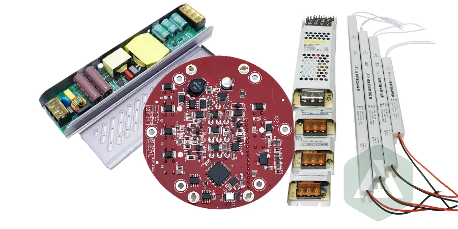
APPLICATION INPUT
The LED load decides the base metal
Aluminum or copper is chosen from the LED wattage and power map, not from a catalog default.

ALUMINUM AND COPPER-BASE LED BOARDS
APTPCB manufactures LED PCBs on aluminum and copper bases for lighting arrays, LED strips, COB modules, high-bay fixtures and automotive lamps. Tell us the LED power map, working voltage and mounting, and engineering confirms the base metal, dielectric and stackup before any material is cut.
Three checks decide whether an LED board quote turns into a luminaire that holds lumen output over life.
Aluminum covers most LED and power boards. Copper is for concentrated heat where aluminum leaves no margin.
A thinner or more conductive layer lowers thermal resistance but has to hold the working voltage.
Electrical, withstand, dimensional and microsection records are listed in the RFQ, not added after shipment.
An LED board is laminated, drilled and routed with a metal backing inside the stack, so the fabricator controls dielectric thickness, hole isolation from the base, burrs on machined strip edges and flatness of long panels. These are the points where LED board lots fail, and none of them show up in an FR-4 quote.
APTPCB reviews the stackup and isolation rules before release, then builds and inspects to the approved drawing. The parameter limits we work to, including dielectric range, copper weights, trace and space, and hole rules, are listed on the capabilities page with dielectric, thickness and tolerance tables.
BEFORE YOU CHOOSE A SUBSTRATE
An aluminum-base LED board fits when heat should go straight through the board into a heatsink or fixture housing and the LED circuit lives on one or two copper layers. If the design needs dense multilayer routing, a single hotspot under one COB array, or ceramic-level temperature and isolation, compare the ceramic, heavy copper and copper coin options in the high thermal conductivity PCB guide first.
For LED-specific tradeoffs, read aluminum vs copper base selection for LED boards and when an aluminum PCB is the right choice for LED and power designs. The parent metal core PCB page covers the full construction family.
RFQ CHECKLIST
A complete package lets engineering quote the right base metal and dielectric the first time. Missing working voltage, LED power map or mounting details are the usual reason an LED board quote comes back with questions.
WHY APTPCB
Among LED PCB board suppliers and LED circuit board manufacturers, you get an engineering review of base metal, dielectric and isolation before the order is released, not a price matched to a W/m·K number. Substitutions, test scope and report formats are agreed in writing, so the lot that arrives matches the LED board that was approved.
The same team quotes FR-4, heavy copper and ceramic builds, which keeps the architecture comparison honest when an insulated metal substrate is not the cheapest way to meet the thermal target. Assembly profiles and thermal interface choices can be reviewed together with the board; see thermal interface material selection for PCB assemblies.
WHERE THE HEAT GOES
The board is one link in the LED heat path. Each interface below is reviewed against the power map before the stackup is frozen.
LED thermal pad to copper
Thermal pad size under the LED, solder coverage, copper area, and via-in-pad or thermal vias where the package allows set how much heat reaches the dielectric. On a circuit board with LED packages, each LED on PCB lands sits over copper sized for the datasheet, and an LED for PCB mounting always ends on metal, never on bare laminate.
Copper through the dielectric
Dielectric thickness and conductivity set thermal resistance, and the same layer carries the isolation requirement.
Base to heatsink
Flatness, surface finish of the metal, TIM, fasteners and pressure decide how well the base dumps heat.

LED PCB MANUFACTURING PROCESS
Each step closes one open question before more material or tooling cost is committed.
Review the use case
LED type and wattage, power map, duty cycle, cooling, voltage and mounting are checked against the drawing.
Confirm base and dielectric
Aluminum or copper base, alloy, dielectric grade and thickness are fixed, with approved substitutes.
Close DFM and isolation
Hole-to-base isolation, keep-outs, creepage, clearance, outline and panel plan are approved.
Laminate, image and etch
Circuit copper is bonded to the dielectric and metal base, then imaged and etched to the approved rules.
Machine and finish
Drilling, routing or V-score through the metal base, burr control on long strip edges, white solder mask and surface finish.
Test and inspect
Electrical test, withstand test where specified, dimensions, flatness and microsections per the plan.
Release the lot
Records are checked against the purchase order, then the lot ships with the agreed documents.
SELECTION MATRIX
Start with aluminum for LED strips, arrays and luminaires. Move to copper only when the LED wattage and thermal path show aluminum cannot hold the junction temperature target with margin.
APTPCB builds and inspects the LED board to the approved drawing and stackup. Junction temperature, photometric output and system safety approval stay with the product owner, because they depend on the LED, optics, cooling and enclosure outside the board.

QUALITY RECORDS
Records are listed in the RFQ so the lot is released against the same criteria the design was approved to.
Stackup, dielectric grade, isolation rules and drawing revision approved and frozen.
Material identity, lamination, etch, machining and finish controlled to the traveler.
Electrical, withstand, dimensional and microsection records checked against the purchase order.
Each application points to a starting base metal; the LED power map confirms it. Whether the drawing says circuit board LED, PCB board LED, PCB LED board, or LED PCB circuit board, the quote covers the same construction — for round boards carrying PCB LED lights, call out the LED PCB diameter and hole pattern, and a PCB for LED lights follows the same base-metal choice. LED PCB board manufacturers differ mainly in how they prove that construction.
Aluminum base with a reflective white solder mask is the usual starting point for long LED strips, backlight bars and linear fixtures.
High-flux COB modules and dense LED arrays are quoted aluminum or copper depending on the power map and spreading needed.
High-bay, street and stadium luminaires run sustained loads where the thermal margin decides base metal and dielectric.
Headlamps and signal modules where vibration, temperature cycling and transients are part of system approval.
PRICE AND RECORDS
Cost and evidence are set by the same stackup decisions, so they are reviewed together.
Quality
Before artwork release
What is closed
• Power map, ambient, cooling and target temperatures.
• Dielectric, copper, base metal, routing and machining.
• Working voltage, creepage, clearance and validation boundary.
Quality
Before shipment
Possible evidence
• Material identification and approved stackup.
• Electrical, withstand, dimensional and microsection records when specified.
• Certificate of conformity and traceability documents requested before build.
Cost
Construction
What raises cost
• Premium dielectric without a demonstrated thermal bottleneck.
• Tight routing, complex insulated holes, local coins or demanding flatness.
• Special reports or tests added after material and tooling are committed.
Cost
Architecture
Useful levers
• Use FR-4 thermal vias or a local copper structure when the heat path is concentrated.
• Standardize outline, mounting, finish and material families across related assemblies.
• Separate qualification evidence from routine lot release when the risk plan permits.
Questions lighting engineers and buyers ask before ordering LED boards.
Upload the fabrication package with the LED power map, working voltage and mounting details. Engineering confirms aluminum or copper base, dielectric, isolation and the lot records before pricing.