
A connector that presses into a PCB needs more than a hole that admits its pin. The finished plated hole, contact design, board construction and insertion process form the connection system. Start with the exact connector's application specification, identify the required finished-hole and board-thickness ranges, then agree the plating, finish, positioning, tooling and verification needed for that part.
Do not select a press-fit hole by subtracting a generic interference allowance from a visible pin dimension. A compliant contact changes shape during insertion, and its qualified interface depends on its complete design. A hole size copied from another connector family can produce excessive force or inadequate contact even when the pins look similar.
For ordinary soldered terminals, see through-hole soldering basics. For the copper land and drilling relationship, see annular rings and drill tolerance. A press-fit hole needs its own identified requirements rather than inheriting the board's ordinary soldered-hole class.

Real PCB photograph by Vishnu Mohanan / Unsplash. It illustrates the board context; the visible openings are not identified as connector-qualified press-fit holes, and their dimensions cannot be established from the image.
What information must come from the connector supplier?
Record the complete connector part number, contact option, application document and revision. A family name or catalog photograph can omit differences in contact size, plating or board requirements. If an approved alternate is proposed, compare its interface requirements before treating it as a drop-in replacement.
Extract the permitted finished-hole interval, relevant pre-plating requirements, copper and surface-finish conditions, usable board thickness and positional requirements. Also identify the insertion and removal instructions, permitted tooling, seating condition and any restrictions on reuse. Keep source requirements distinguishable from manufacturing proposals and product-owner decisions.
A press-fit electrical terminal is also different from a plastic boardlock or a mechanical locating peg. A connector can contain several attachment types. Mark them individually so that a non-plated locating feature is not mistakenly processed as a conductive press-fit hole, or an electrical contact is not assigned an ordinary mechanical clearance hole.
STMicroelectronics' TN1250 mounting instructions illustrate the importance of part-specific rules: that document gives defined board and insertion conditions for its ACEPACK modules and restricts pressing a removed module in again. Those conditions should not be transferred to an unrelated connector. A general claim that press-fit connections are reworkable does not authorize reuse of the selected contact.
Distinguish drill diameter, finished hole and the accepted process
The drill creates a manufacturing opening. Hole preparation, copper deposition and surface finishing affect the condition encountered by the pin. The finished plated hole is therefore not interchangeable with the nominal drill-tool diameter.
Identify the press-fit population in the fabrication drawing and drill table. Show its finished-hole requirements and the controlling application document. Ask the fabricator to confirm a route that can satisfy them. If a connector specification also constrains the initial drilled diameter, preserve that requirement and resolve it with the proposed process; do not discard it because finished dimensions are also specified.
Define the required hole-wall finish separately from the finish on other soldering pads. An ENIG selection for surface-mount lands does not automatically approve ENIG in every press-fit system. Similarly, a preference for immersion tin in one product document does not make it mandatory for every contact design.
Where a requirement concerns a local minimum copper thickness, a panel-average value answers a different question. Agree what is measured, where and on which samples. A quoted capability without the measurement definition may leave the critical interface unverified.
Put the interface requirements in one hole-class record
Identify the press-fit holes as a distinct class, such as PF1, and associate that class with the exact contact option. The example below shows how to organize the requirement; the hypothetical dimensional interval in the next section supplies only its diameter example. Populate the other requirements from the released contact and board documents before fabrication.
| PF1 requirement | Controlling information | Evidence to agree |
|---|---|---|
| Finished hole interval | Exact contact application drawing; the full lower and upper limits | Finished-hole measurement with identified features and acceptance policy |
| Initial drill, if constrained | Contact document plus the fabricator's approved processing route | Manufacturing record for the specified hole population |
| Hole-wall copper | Required local minimum or other explicitly defined thickness criterion | Measurement location, specimen identity and sampling |
| Hole-wall finish | Finish system and condition permitted by the selected contact | Identified process and applicable inspection record |
| Board thickness and usable contact depth | Contact application drawing, finished board definition and seating requirement | Board dimension and assembly seating checks |
| Pattern position | Connector datum, hole-to-hole position and locating features | Pattern measurement in the agreed coordinate frame |
| Insertion and reuse | Exact contact's tool, support, seating and repair instructions | Approved setup and agreed insertion/inspection records |
For a drawing, reference PF1 in the hole table and place the contact document identifier and revision beside it. Do not hide a hole-wall finish requirement inside a general note for surface-mount pads. If one field conflicts with the board specification, resolve that field before release rather than adding a generic “press-fit compliant” statement.
Check the complete dimensional range
A shared nominal value is insufficient. The proposed PCB limits must meet the applicable connector limits, with the agreed measurement and acceptance policy. Review board thickness separately from hole diameter, and evaluate the complete hole pattern rather than one representative nominal hole.
Consider a hypothetical connector whose approved finished-hole interval is 0.98–1.04 mm. A PCB note of 1.01 ± 0.05 mm allows 0.96–1.06 mm. The nominal is centered, but both ends exceed the assumed allowed interval. The discrepancy is 0.02 mm at each boundary.
A proposed note of 1.01 ± 0.02 mm permits 0.99–1.03 mm, which lies within the assumed interval. That arithmetic screens the specified dimensions only. It does not establish manufacturing capability, measurement uncertainty, hole-wall quality or a qualified connection. All values here are invented for comparison and must not be used as a connector recommendation.
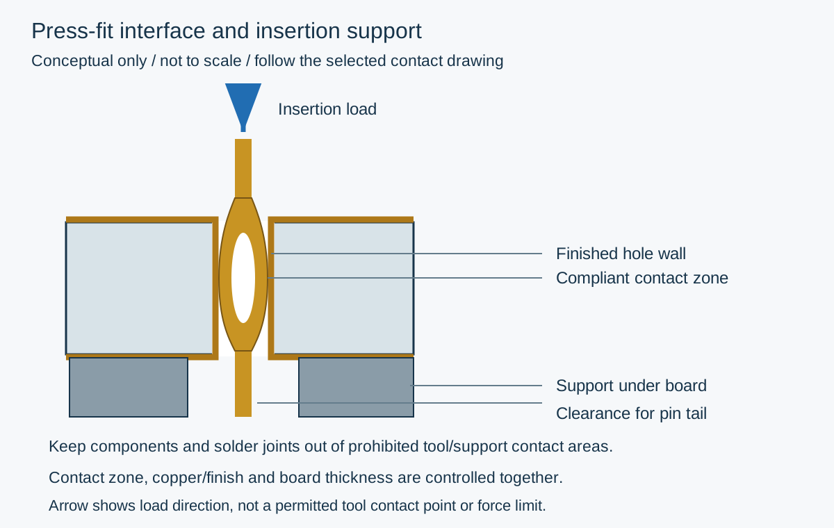
Conceptual section, not to scale or a tooling drawing. It separates the compliant contact zone, conductive hole wall and board support; the selected connector specifies the actual geometry, permitted load points and seating position.
Before tightening the drawing tolerance, ask whether the fabricator can control and demonstrate it for the actual construction and quantity. A tighter callout can change inspection, process development and cost. It is not a substitute for discussing feasibility or for resolving a mismatch in the original connector selection.
Plan the insertion load path before populating the board
Review how the tool applies force to the connector and how the board reacts that load. Show the underside as well as the component side. Support must avoid prohibited contact with components, solder joints and protruding leads while allowing the pin tails and connector geometry to move as intended.
Do not wait until a populated assembly reaches the press to discover that its support region is occupied. Include fixture access in the assembly drawing and review it with the intended assembly sequence. A drawing courtyard alone may not describe the tool's working envelope.
Use the selected component's seating and insertion instructions. An arbitrary stop based on overall press travel may not prove that every compliant zone is in its intended position. Board bending, contact misalignment and uneven loading can also make a connector appear close to seated while leaving an unacceptable interface.
If force and displacement are monitored, establish the expected process window using the approved part, board and tooling. A peak value cannot fully describe where abnormal resistance occurred. Retain the evidence needed to investigate a change in the trace, rather than accepting any insertion whose final height looks plausible.
Separate receiving, insertion and release decisions
Define who can accept each stage and what happens when evidence is missing. This makes the process actionable when a real lot differs from the drawing or an insertion behaves unexpectedly.
| Observation | Immediate disposition | Evidence needed before release or restart |
|---|---|---|
| Board report lists only ordinary PTH limits | Hold the press-fit population for clarification | Identified dimensions and wall/finish evidence against the controlling requirement |
| Finished holes meet limits but connector pattern will not align | Stop before applying force | Pattern position, locating datums, connector condition and board orientation review |
| Insertion trace changes abruptly from the approved process | Stop and segregate the affected assemblies | Trace, tooling/setup records, board lot and component lot; engineering disposition |
| Connector appears seated but hidden interface damage is suspected | Keep the assembly out of release | Approved investigation, potentially including representative sectioning or other specified checks |
| A connector is removed during troubleshooting | Identify both board and component as rework candidates | Product-specific removal/reuse instructions and an approved rework disposition |
Assign limits, sampling and decision owners to this framework in the agreed control plan; confirm which records the supplier will deliver.
Receiving evidence addresses the bare board. Insertion evidence addresses the assembled connection. Product qualification addresses performance under the intended electrical, mechanical and environmental conditions. Do not use a passing continuity check to replace all three. An electrically continuous connection can still have an unacceptable mechanical or hidden-interface condition.
What should a first-build evaluation include?
Use the actual connector option, released board construction and intended tooling. Record board and component lot identities so the evaluation can be traced. Compare the pre-insertion board evidence with the process records and the resulting seating condition.
Agree in advance whether dimensional inspection, force/displacement records, electrical checks, retention evaluation or destructive examination are needed. If sectioning is selected, identify the hole population, section orientation and question being investigated. A section through an unrelated via does not establish the condition of a press-fit barrel after insertion.
Keep the trial records with the board and component lot identities. Re-evaluate affected checks after a tooling, insertion-setting or support change; use the exception table above to disposition abnormal results.
The PCB lot-traceability discussion helps organize records, while microsection coupon strategy addresses destructive evidence planning. Neither substitutes for the chosen contact's application specification.
Compare quotations by the work included
Separate bare-board fabrication from connector supply, insertion, fixture development, process trials and qualification. A quotation for tight-tolerance holes is not necessarily a quotation for an assembled press-fit connector. Likewise, an insertion price may exclude board measurements or product qualification.
Send the connector part and revision-controlled application document, board data, identified press-fit holes, required finished dimensions, plating/finish conditions and board-thickness interval. Include positional requirements, populated-board keepouts and the proposed support arrangement where available.
Ask which measurement records, trials and insertion records can be provided and at what scope. Keep unresolved points visible in the quotation rather than allowing a general statement such as “press-fit capable” to stand in for acceptance of the actual requirements.
Request a quote or contact the team with the board package and selected connector documentation. Agree the feasible construction and available assembly deliverables for the project. Changes to the connector interface, repair permissions and final qualification require approval by the product design authority.
Common release questions
Can the ordinary via tolerance be used for press-fit holes?
Only if the complete specified range and all other conditions satisfy the selected contact's requirements and the manufacturing process can demonstrate them. Naming a hole a via does not qualify it for a press-fit connection.
Can a larger hole solve excessive insertion force?
Do not enlarge the hole without an engineering review. Excess force can arise from dimensions, plating, alignment, tooling or setup. Enlarging the hole may remove the interference needed by the intended contact system.
Can a removed contact be inserted again?
Follow the exact product's instructions and approved repair process. Do not assume a universal number of reuse cycles or that removing a contact leaves the original hole suitable for another insertion.
Technical reference basis
STMicroelectronics, TN1250, Press-fit ACEPACK power modules mounting instructions, DocID030935 Rev 1, provides a product-specific example of board and insertion controls. Würth Elektronik, Press-Fit Technology, describes the connection principle. For production, the selected connector's current application specification and the agreed board/assembly acceptance plan control.