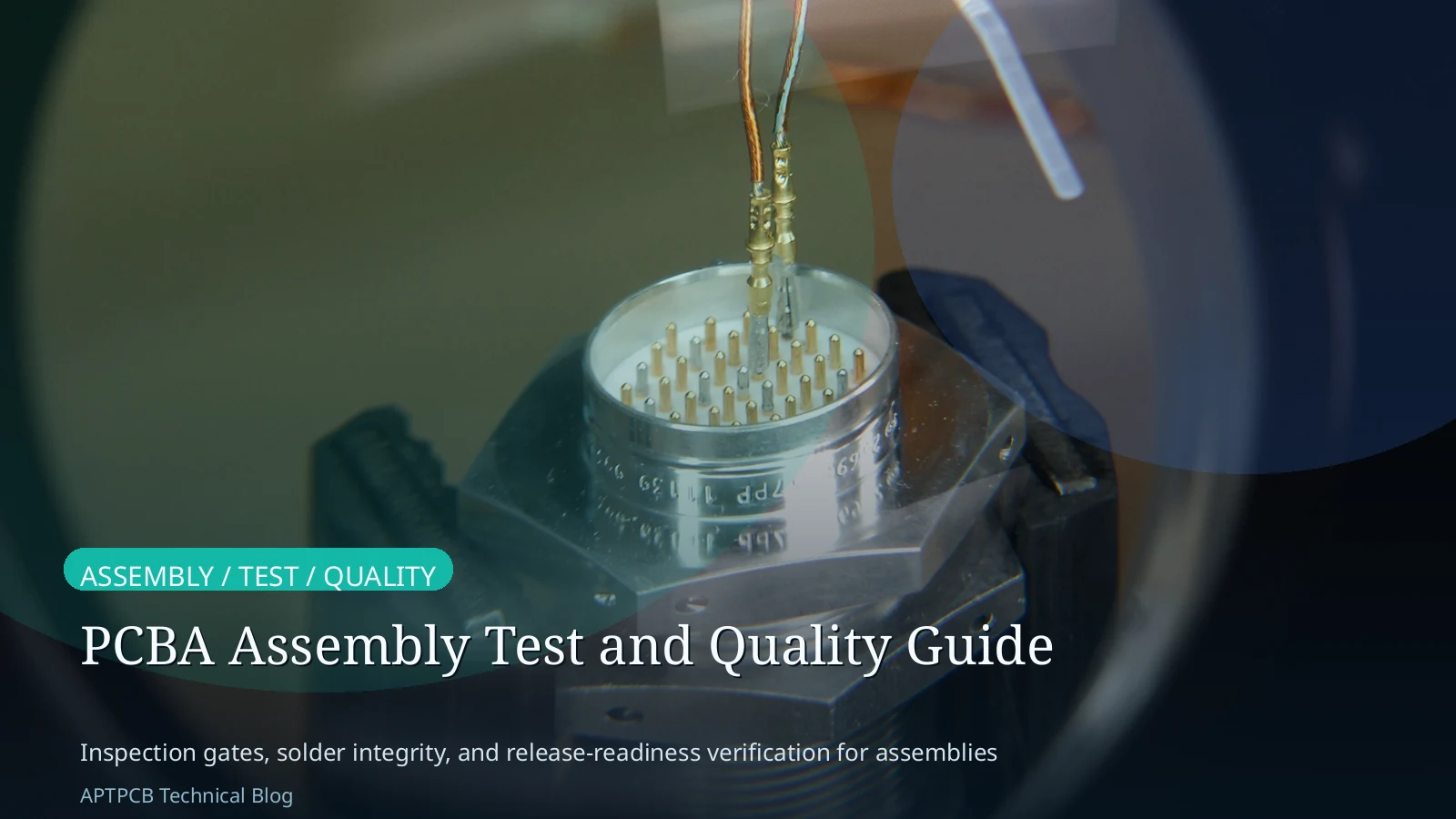
- PCBA assembly quality should be treated as a layered release system, not as one vague promise that a board was simply "tested."
- The most useful boundary is to separate build inputs, inspection layers, electrical verification, functional behavior, and shipment release gates.
- A board can pass one gate and still fail the next because SPI, AOI, X-ray, ICT, flying probe, FCT, FAI, and final inspection answer different questions.
- The safest public framing is to explain which method is responsible for which defect class or release decision, and to avoid implying that every program gets every test layer.
Quick Answer
PCBA assembly test and quality are easiest to manage when the team reviews the build in order: BOM and component control, assembly definition, inspection stack selection, electrical or functional verification, and final release governance. The better question is not "Was the board tested?" but "Which gate was responsible for catching which risk before shipment?" That framing prevents AOI, X-ray, ICT, flying probe, FCT, FAI, and traceability from being collapsed into one generic claim.
If your program already depends on inspection planning or release evidence, start with Testing & Quality, Turnkey Assembly, and AOI Inspection before using this guide to classify the deeper assembly and test burden.
Table of Contents
- What counts as PCBA assembly test and quality here?
- What should engineers review first?
- Why assembly input control starts before test
- How inspection and electrical methods divide responsibility
- Why release gates and traceability stay separate from defect detection
- Which project types change the review order?
- What should be frozen before RFQ, first build, or shipment release?
- Next steps with APTPCB
- FAQ
- Public references
- Author and review information
What counts as PCBA assembly test and quality here?
Here, PCBA assembly test and quality means the full board-level control path from build inputs to shipment release.
That includes:
- BOM and component sourcing control
- assembly drawing and process-definition clarity
- incoming quality checks
- SPI, AOI, and X-ray where the build requires them
- ICT or flying probe for electrical defect screening
- FCT for powered behavior validation
- FAI, final inspection, traceability, and release documentation
Those layers belong together, but they should not be treated as interchangeable.
The common mistake is to write as if:
- inspection means the same thing as testing
- electrical test means the same thing as functional proof
- traceability means the same thing as quality assurance
- final inspection means the same thing as zero-defect release
Those are not the same decisions.
The better question is:
Which quality layer owns which risk, and what evidence is still needed before the board can be released?
What should engineers review first?
Start with these five boundaries:
- build-input control
- inspection-layer selection
- electrical versus functional verification
- release-gate governance
- evidence boundary
That order matters because many assembly problems appear before the first powered test ever begins.
The first engineering questions are usually:
- Is the BOM stable enough and traceable enough to support the intended build?
- Does the assembly package define placement, polarity, mixed-process handling, and reflow assumptions clearly enough?
- Which defects need optical inspection, which need hidden-joint inspection, and which need electrical verification?
- Is this build better suited to fixture-based ICT or fixture-free flying probe?
- Does the customer need powered functional proof, or only manufacturing-defect screening plus release inspection?
| Review boundary | What it answers | What it does not prove |
|---|---|---|
| Build inputs | Whether the board can be assembled from the intended materials and instructions | That the assembled board will pass electrical or functional validation |
| Inspection layers | Whether visible or hidden assembly defects can be screened at the right stage | End-use behavior in the target system |
| Electrical verification | Whether opens, shorts, polarity issues, or component-level faults are being screened | Full powered functionality or field reliability |
| Release governance | Whether incoming, first-article, final inspection, and traceability gates are complete | That any one gate can replace the rest |
| Evidence boundary | Which claims the board-level package can support before shipment | System qualification, compliance, or lifetime proof by default |
Why assembly input control starts before test
PCBA quality starts upstream of AOI, ICT, or FCT.
If the BOM, assembly instructions, and process assumptions are weak, later test stages are forced to diagnose problems that were created much earlier.
BOM and sourcing control set the first quality boundary
The BOM is not only a purchasing list. It is also part of the traceability and release posture for the build.
Questions that belong here include:
- whether approved parts and alternates are explicit
- whether lifecycle or authenticity concerns are already known
- whether polarity, value, package, and sourcing assumptions are stable
- whether the build is turnkey, consigned, or mixed
When those items drift, test results become harder to interpret because the board may no longer match the intended input set.
Related reading:
Assembly definition controls whether the line is testing the right build
An incomplete assembly package creates avoidable ambiguity around:
- reference designators and placement notes
- polarity and orientation
- mixed SMT and THT routing
- special handling or selective-process branches
- whether the board is still in NPI, pilot, or a more stable repeat build
That is why assembly quality should never be framed as only a downstream test question.
| Input area | Why it matters early | What goes wrong when it stays vague |
|---|---|---|
| BOM structure | Keeps the component set stable and traceable | Wrong value, wrong package, or unclear alternate usage can surface late |
| Assembly drawing | Aligns human and machine interpretation of the build | Placement, polarity, and process intent drift |
| Mixed-process planning | Separates SMT, THT, selective, and hand-assembly burdens | The board enters inspection without a clean process path |
| DFM / DFA posture | Confirms manufacturability and assembly readiness before release | Later test stages spend time diagnosing preventable build issues |
For package-cleanup topics, see:
The governing rule is simple:
when the assembly package is unstable, later test layers become slower and less decisive.
How inspection and electrical methods divide responsibility
The inspection and test stack works best when each method keeps its own boundary.
Inspection layers are not interchangeable
SPI, AOI, and X-ray do not answer the same question.
| Method | What it mainly answers | What it does not prove |
|---|---|---|
| SPI | Whether solder paste deposition is in control before placement and reflow | Visible assembly correctness after reflow or board electrical behavior |
| AOI | Whether visible geometry, polarity, placement, and solder features look acceptable | Hidden-joint integrity or powered functionality |
| X-ray | Whether hidden solder joints and concealed defect areas need inspection evidence | That visible inspection or functional validation can be skipped |
That distinction matters because a board can pass optical review and still fail later electrical verification. It can also look electrically stable at one layer while still needing hidden-joint review in dense-package areas.
For more focused inspection topics, see:
- AOI Inspection
- AOI Inspection for PCBA
- AOI and SPI Best Practices
- SPI vs AOI in PCBA
- X-Ray Inspection
ICT and flying probe solve different electrical-test problems
The internal quality stack separates fixture-based ICT from fixture-free flying probe.
That boundary is operationally useful:
- ICT fits programs that can justify fixture-backed node access and repeatable electrical screening
- flying probe fits changing, low-volume, or launch-stage builds where fixture commitment is less attractive
Neither one should be described as a universal replacement for the other.
| Electrical method | Best public framing | What it does not imply |
|---|---|---|
| ICT | Fixture-based electrical verification for assembled boards with suitable access and test planning | That every design has the needed access or should use the same fixture model |
| Flying probe | Fixture-free electrical verification for prototypes, small batches, or changing builds | That it is simply the same thing as ICT under a different name |
Related reading:
Functional test belongs after the defect-screening conversation
FCT answers a different question from ICT or flying probe.
ICT and flying probe are primarily about electrical connectivity and manufacturing-defect screening. FCT is about whether the assembled board behaves correctly in its intended powered context.
That means:
- a board can pass AOI and still fail ICT
- a board can pass ICT and still fail FCT
- a board can pass electrical screening and still need final release review
The safer explanation is:
inspection, electrical test, and powered behavior validation are related layers, not one interchangeable test bucket.
Why release gates and traceability stay separate from defect detection
Release confidence accumulates across several gates.
Incoming quality control, first-article inspection, final inspection, cleanliness review, and traceability should be treated as governance layers around the build, not as synonyms for AOI or ICT.
| Release gate | What it answers | What it does not prove |
|---|---|---|
| Incoming quality control | Whether materials and incoming parts are accepted into the build flow | That the assembled board will perform correctly after assembly |
| First-article inspection | Whether the first build confirms setup and launch assumptions | That later production drift cannot happen |
| Final inspection | Whether end-of-line acceptance checks are complete before shipment | That every upstream process issue was impossible |
| Cleanliness review | Whether contamination-related concerns are being checked where relevant | That every reliability question is closed for every program |
| Traceability | Whether the build history, component context, and release evidence are recoverable | That documentation alone guarantees product quality |
This boundary matters because traceability is evidence, not a defect-detection method by itself.
The same applies to FAI and FQI:
- FAI does not replace upstream inspection and test
- final inspection does not replace electrical verification
- build history does not replace a real release decision
For gate-specific topics, see:
- Incoming Quality Control
- First Article Inspection
- Final Quality Inspection
- Testing & Quality
- Cleanliness Testing for PCB
The governing rule is:
release gates decide whether the evidence is complete enough to ship; they do not erase the need for the underlying evidence itself.
Which project types change the review order?
Different build conditions move different quality layers to the top of the review.
| Project type | What moves to the top of the review | Deep-dive page |
|---|---|---|
| Prototype or changing NPI build | fixture-free electrical verification, assembly-definition stability, first-build learning | /en/blog/ict-vs-flying-probe |
| Dense package or hidden-joint assembly | X-ray need, optical boundary limits, hidden-joint evidence | /en/blog/xray-inspection |
| Paste or optical-defect-sensitive SMT build | SPI and AOI role separation, visible-defect screening order | /en/blog/spi-vs-aoi-when-to-run-each-in-pcba |
| Mixed SMT and THT assembly | process-branch clarity, assembly package definition, inspection routing | /en/blog/mixed-assembly-planning |
| Documentation-heavy release | BOM control, assembly drawing completeness, FAI and final release governance | /en/blog/assembly-bom-best-practices |
| Assembly-readiness cleanup | manufacturability, component placement, and DFA alignment before test execution | /en/blog/design-for-assembly-checklist |
That table helps separate a quality discussion by build type instead of by generic test buzzwords.
What should be frozen before RFQ, first build, or shipment release?
Before serious RFQ, first build, or shipment release, freeze the items that change the quality path:
- the BOM structure, sourcing posture, and approved alternates
- the assembly package, including drawings, polarity notes, and mixed-process assumptions
- the inspection intent, especially where SPI, AOI, or X-ray are expected to answer different defect classes
- the electrical-test posture, including whether the build should rely on ICT, flying probe, functional test, or a scoped combination
- the release-gate package, including IQC, FAI, final inspection, cleanliness, and traceability expectations
- the evidence boundary between manufacturing release, customer acceptance, and any later system-level qualification
If those items are still moving, the board can still be built, but the quality path is not yet fully defined.
Next steps with APTPCB
If your program is being slowed by an unstable BOM, unclear assembly drawings, uncertain SPI or AOI coverage, hidden-joint inspection questions, ICT versus flying-probe tradeoffs, or missing release-gate evidence, send the Gerbers, BOM, assembly package, and test expectations to sales@aptpcb.com or upload the files through the quote page. APTPCB's team can review the build path and point out whether the main risk sits in input control, inspection planning, electrical verification, or shipment-release governance.
If you need to go deeper before release, review:
FAQ
Is AOI enough to say a PCBA is fully tested?
No. AOI is an optical inspection layer. It does not replace hidden-joint review, electrical verification, functional test, or final release governance.
Should every PCBA use ICT and FCT?
No. The right stack depends on the build stage, design stability, access model, and release intent. Different programs need different combinations of inspection and test layers.
Is flying probe just a lower-cost version of ICT?
No. Flying probe and ICT use different access and setup models. They may solve overlapping electrical-screening problems, but they are not the same method.
Does first-article inspection replace final inspection?
No. FAI confirms early build and setup assumptions. Final inspection is a separate shipment-release gate later in the flow.
Does traceability prove reliability by itself?
No. Traceability records build history and release evidence. It does not replace defect detection, functional validation, or any separate reliability evaluation.
Public references
APTPCB Testing & Quality
Supports the layered PCBA quality flow across inspection, electrical test, and release governance.APTPCB AOI Inspection
Supports AOI as a visible-defect inspection layer rather than a universal test claim.APTPCB X-Ray Inspection
Supports hidden-joint and concealed-defect inspection boundaries.APTPCB ICT Test
Supports fixture-based electrical verification for assembled boards.APTPCB Flying Probe Testing
Supports fixture-free electrical verification for changing or lower-volume builds.APTPCB First Article Inspection
Supports first-build confirmation as a separate release gate.Koh Young: Solder Paste Inspection Technology
Supports SPI as an upstream paste-measurement and print-process control layer.Koh Young: Automated Optical Inspection Technology
Supports AOI as an optical method for assembled geometry and solder features.Keysight: In-Circuit Test Systems
Supports ICT as a production-line electrical fault-screening method.
Author and review information
- Author: APTPCB PCB and PCBA process content team
- Technical review: PCBA assembly, inspection, electrical-test, and release-governance engineering team
- Last updated: 2026-05-13